
Machining Deep with Solid Carbide Drills
A new twist on deep-hole drilling strategies for mold machining.
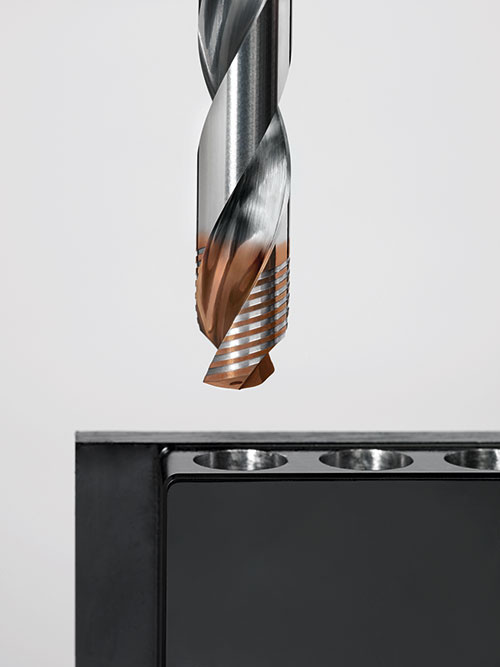
With advances in technology, solid carbide drills are now capable of machining depths ranging to 70xD. Images courtesy of Walter USA LLC.
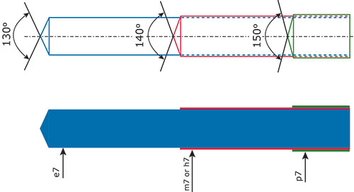
Figure 1 - For deep-hole drilling, it's critical that all drill point angles and diameter tolerances be coordinated.
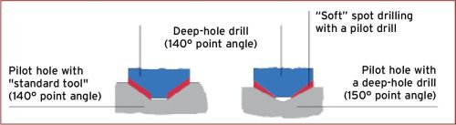
Figure 2 - Using a pilot drill with the correct point angle can improve a deep-hole drill’s performance and life.
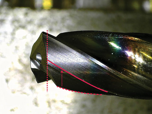
Figure 3 - By positioning the second margin in the center of the drill land, it can engage in the cut much sooner.
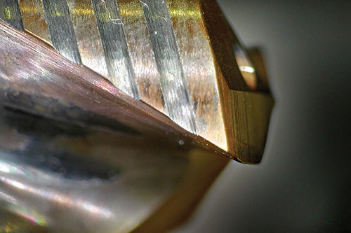
Figure 4 - Orienting the margins perpendicular to the flute creates a larger margin area, which can better support the drill point.


Plastic injection molds must be made from materials with high hardness to resist abrasive wear and with elevated toughness to handle the high pressures of the molding process. Molding plastic also presents a cooling challenge, and to help control the cooling rate of the plastic, the molds commonly are designed with coolant passages. These coolant passages typically are created by deep-hole drills designed to produce holes with very high length-to-diameter ratios. Drilling a hole with a 16× length-to-diameter ratio or longer requires a special type of drill and extra considerations in the drilling strategy.
While gundrilling has proven to be an effective process for creating these types of holes, it is also an extremely slow process compared to drilling using solid carbide drills. Thanks to advances in cutting technology, these types of drills are now capable of machining depths ranging to 70×D, which was previously only considered possible with gundrilling.


A gundrill’s advancement per revolution and cutting speed yield a typical feed rate of 4 to 6 inches per minute, while a solid carbide drill can run at higher advancement per revolution and higher cutting speeds due to the material’s inherent strength and the geometry of the drill’s point and body. Feed rates of 35 inches per minute and higher are not uncommon with solid carbide deep-hole drills. Increased feed rates result in faster production times and increased part production by each machine, thereby lowering the cost of manufacturing.
Here are some advancements in technology and machining strategies that can improve deep-hole drilling:
Diameter tolerance. A pilot hole should be used when drilling holes at a depth equal to or greater than 16×D. The pilot hole acts as a guide to help stabilize the longer drill at the beginning of the drilling process. Drill manufacturers offer special pilot drills specifically for creating this initial hole that are uniquely designed for this task with regards to the point angle and the diameter tolerance.
The diameter tolerance of a pilot drill is typically a unilateral (plus/plus) tolerance, for example, an ISO tolerance class of p7 that allows the user to select a pilot drill with the same nominal diameter as the deep-hole drill (see Figure 1). This tolerance ensures that the pilot hole is properly sized to support the drill and not cause interference.
Point angle. When drilling into a pilot or pre-machined hole, the angle of the drill point should be smaller than that of the previous drill (see Figure 2). This is to minimize the force load on the drill as the point penetrates the material. If the point angles match exactly, this may cause a spike in the torque applied to the drill, which could break the drill or cause chatter.
Typically, pilot drills have a standard 145- to 150-degree point angle. Since hole depths ranging to 30×D can be prepared by only using a 2×D pilot hole, drills in the range of 16× to 30× the length-to-diameter ratio should have a point angle of 135 to 140 degrees. This point angle configuration allows any drill to 30×D to work in sync with the standard pilot drill.
Solid carbide drills designed for lengths in excess of 30×D should use a 125- to 130-degree point angle. Drills in this length-to-diameter ratio range cannot be used with a 2×D pilot hole. Instead, the pilot hole should also be prepared with a second pilot hole, created with a drill in the 16×D to 20×D ratio.
Tools designed with varying point angles can stop the drill point from matching the angle of the previous drill point, which causes a large torque spike at initial engagement at the bottom of the pilot hole. If these factors are considered when solid carbide deep-hole drills are designed, the tool selection process is much clearer, as the end user only needs to be concerned with selecting tools based on the nominal drill size.
Margin support. Once the drill point becomes fully engaged, the drill is supported on its margins (the bearing surface on the outside diameter of the drill body that runs along the edge of the flute). For deep-hole drills, two margins per cutting edge is standard. However, due to the geometry of the clearance angles and the gash on the drill point, the second margin may not be close enough to the point, and therefore cannot engage until much later (approximately 1 to 2×D). This leaves the drill point with less than maximum support in this critical range, until the second margin can become engaged (see Figure 3).
To combat this issue, newer deep-hole drills have moved the second margin from the trailing edge to the middle of the drill land. This moves the start of the second margin closer to the drill point and allows it to become fully engaged much earlier, quickly allowing full support to guide the drill point.
Radial or perpendicular margins. A new concept in solid carbide drill design involves an innovative land design that orients the margins radially or perpendicular to the flute rather than parallel to the flute (see Figure 4).
Configuring the margins in a radial orientation around the drill point eliminates the need to wait for the second margin to engage. Solid carbide material provides support directly behind the cutting edge and continues for the full width of the land, which immediately provides maximum support and guidance to help produce the straightest possible hole.
Strong cutting edges. Additional solid carbide material located behind the cutting edge makes a stronger tool, because that added material is positioned to directly oppose the largest cutting forces. A stronger cutting edge design offers two benefits: 1) the machinist can take advantage of an overall increase in production rates by using higher advancement per revolution, and 2) longer tool life can be expected due to the additional material, which means greater production runs, more machine uptime and decreased cost to the manufacturer.
Pushing the Limits
Molds have many complex shapes and designs, but most also have one common feature: deep holes through the entire mold that allow fluid to control the cooling rate of the plastic as it is being formed. Creating these coolant holes requires special drills that have extraordinary length-to-diameter ratios. With advancements in materials, tool designs and machining strategies, these drills now can perform at lengths never before thought possible. By making the drills from solid carbide, the tools can be pushed with higher cutting speeds and feed rates, and generate faster production rates, yielding easier part production for the machinist and more profit for the shop owner.


Related Content

How a Small Programming Change Cuts Cycle Time in Half
Overriding the CAM system when milling a series of lifter pockets helps to improve metal removal rate and increase feed rates.
Read More
4 Cutting Tool Challenges and Solutions
A combination of cutting tool carbide, coating and geometry helps tackle four mold machining challenges and improve cutting performance.
Read More
6 Ways to Optimize High-Feed Milling
High-feed milling can significantly outweigh potential reliability challenges. Consider these six strategies in order to make high-feed milling successful for your business.
Read More
How to Use Continuing Education to Remain Competitive in Moldmaking
Continued training helps moldmakers make tooling decisions and properly use the latest cutting tool to efficiently machine high-quality molds.
Read MoreRead Next

Improved Graphite Electrode Machining
When a more productive and cost-effective method of machining graphite electrodes was needed, this moldmaker turned to a solid carbide modular milling system.
Read More
Your Guide to Smarter, Faster Mold Design
Dive into expert-curated content delivering proven solutions for mold optimization, manufacturability and precision performance.
Read More
How to Use Continuing Education to Remain Competitive in Moldmaking
Continued training helps moldmakers make tooling decisions and properly use the latest cutting tool to efficiently machine high-quality molds.
Read More