
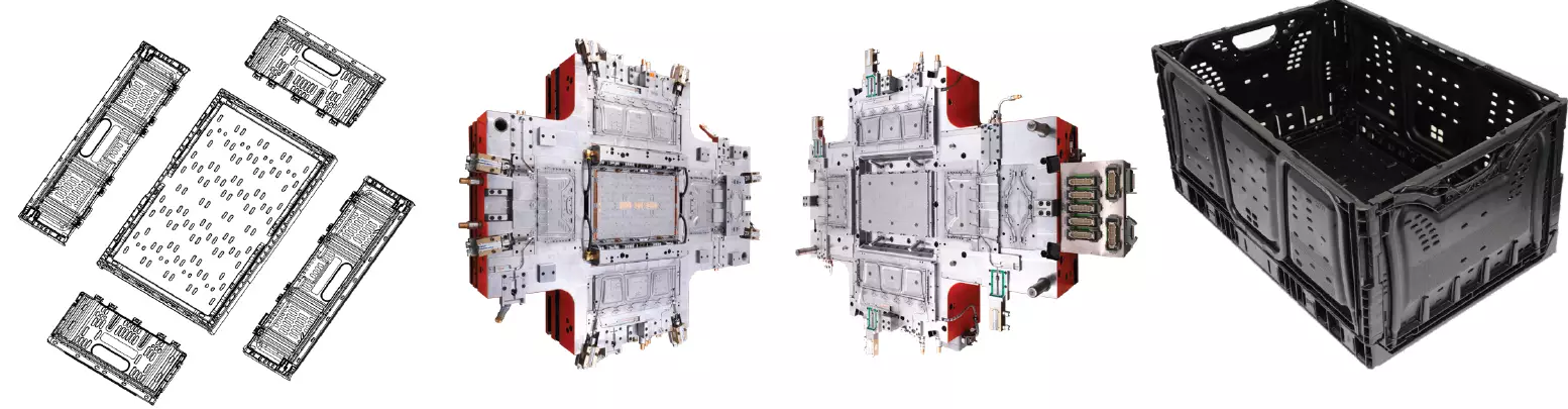


A thorough plastic part design review ensures that you and your customer agree on the plastic part for the mold build project. Photo Credit: Haidlmair GmbH
A fully described plastic part is the most crucial information for a mold build project. An incomplete part drawing can create countless problems in the mold design process, waste a lot of precious time and cause numerous issues when the mold is completed and commissioned at the customer’s facility.
Spending extra time at the beginning of the mold design project to create a fully described part, which considers all aspects of the mold design, can save tens of thousands of dollars for the moldmaker, and hundreds of thousands of dollars for the molder and OEM.


While creating the plastic part drawing, the designer has the best opportunity to decide on the most suitable design for the mold and/or to make suggestions on how the product design might be modified to improve productivity and simplify the mold design; in turn, simplifying the mold design reduces mold costs.
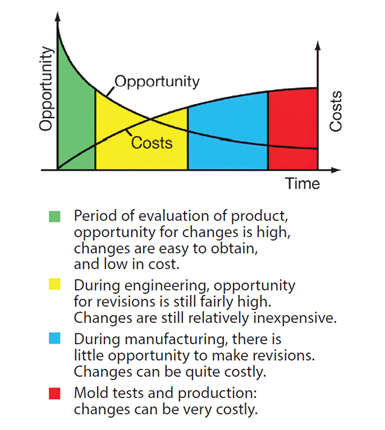
Figure 1. Cost and opportunity for change over the time of a mold build project. Photo Credit: Injection Mold Design Handbook.
The cost versus opportunity graph (see Figure 1) shows the value of ensuring the part drawing is critiqued early in the project.
Making improvements, revisions and selections at the outset of a project offers the most significant potential to affect the final outcome, including the part cost.
Once the mold design concept has been agreed upon, and as engineering of the mold progresses, the opportunity to make conceptual changes or improvements diminishes and any costs associated with it will increase.
By the time the project reaches completion, the opportunity to make changes is low, and any costs could add up to 150 times the cost of a change in the design phase!
Key Components of a Plastic Part Drawing
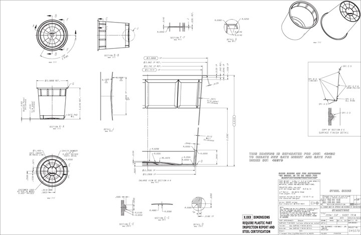
At the beginning of a mold build project, the customer may have only part samples, a CAD model or a 3D-printed model of the part they want to mold. While this may be advantageous to better visualize the product, it is absolutely necessary to have a complete detailed drawing of the product to minimize risk for all parties involved in the final decision. This drawing should show all features, tolerances and specifications. An example of a complete part drawing is shown in Figure 2.
A complete plastic part drawing should contain the following information at a minimum:
- A 3D solid model of the part or a completely dimensioned 2D plan and section view;
- Any small or intricate details blown up into additional sections or views, for example, ribs or bosses;
- A detail showing any fits to other components;
- Engraving, artwork and cavity numbering;
- Mold label information (if in-mold labeled);
- Surface finishes;
- Any stacking details (if appropriate);
- Part weight (using an assumed plastic density);
- Part volume (if filled and weighed);
- Center of gravity (if appropriate);
- Identification of plastic or steel sizing;
- Identify all split lines and parting lines, including any intentional mismatches.
Once the part drawing is completed, it must be reviewed with the customer and internally at the moldmaker’s facility.
In today’s fast-paced environment the mold designer must sometimes work in parallel with the customer by completing some of the mold design concepts while the part is still being finalized.
Review Checklist for Plastic Part Design
The following checklist can be used as a part drawing critique during the part design review meetings. Embedding a part design critique meeting into your mold design process can save thousands of dollars and weeks of mold build time.
Answering the questions below will ensure that a proper review of the part takes place and that all critical aspects of the part design have been considered and approved by the customer, and are acceptable to the moldmaker.
1. Is the drawing a plastic part drawing or “steel part drawing?” Is this clearly marked on the part drawing? A steel part drawing is the plastic part with shrinkage dimensions applied, so that the mold designer does not need to add shrinkage. This is often used when the shrinkages are not uniform around the part
2. Is the shrinkage defined? Is there one (1) general shrinkage or multiple shrinkages?
3. Are part weight and tolerances clearly shown?
4. Is all geometry defined (radii, angles and so on)? Are complicated details called out in blowups and section views such that the part design is fully understood?
5. Are all negative drafts on the part eliminated? Are all drafts defined, including ribs, bosses and sidewalls?
6. Are there any sharp corners on the drawing? If possible, a minimum radius of 0.25 millimeter (0.010 inch) should be used on plastic parts. A radius of 0.8 millimeter (0.030 inch) is the minimum recommended radii as the stress concentration is mostly eliminated above this.
7. Are the parting lines and all split lines defined? Are all intentional mismatches between core and cavity shown and defined?
8. Has a CAE flow analysis been conducted? Will the part fill and avoid any problematic weld lines and potential voids? Review the L/t ratio (length of flow/thickness) and confirm it is acceptable.
9. Are all venting locations shown and vent sizes defined?
10. Are all potential pinch points to the flow of the molten plastic eliminated? For example, are all thick sections that may cause “race tracking” of molten plastic eliminated?
Making improvements, revisions and selections at the outset of a project offers the most significant potential to affect the final outcome, including the part cost.
11. Are horizontal sections (bottom/stack shoulder) 0.05 millimeters thicker to account for stack compression and ease of filling?
12. Are locations where sinks may occur (like at the end of a rib) called out? Are thick-to-thin transitions designed correctly to reduce sinks?
13. Is the gate position defined and an acceptable gate vestige called out? Usually, the acceptable vestige for a valve gate is flush with the molding surface or slightly into the molding surface to prevent interference. Normally acceptable vestiges are around 50–75% of the gate diameter if the gate is a hot tip. Is a dimple needed to hide the gate vestige?
14. Is allowable warpage called out?
15. Do the parts need to stack and de-nest? If so, is the stacking height shown, and is there a diagram showing the stacking of the parts?
16. Are all ribs and bosses shown in plan view, top view and side view?
17. For multi-cavity molds, is the cavity numbering identified?
18. Are all molding surface finishes defined?
19. Is all required engraving shown on the part? For example, does the engraving need to be mirrored on the molding surface?
20. Is any geometry to be left off until after the first test (pull rings, engraving)?
21. For critical dimensions, will the dimension be left “steel-safe” for the first run so that the sizing can be adjusted?
22. Have any deviations to standard tolerancing of molding surfaces and fits been noted?
23. Has the part drawing been reviewed with the customer and signed off?
(Click here for a Plastic Part Design Review Checklist to record
“Items” and “Completed (Y/N) / Risk Mitigation” information.)
Time for Approval
Once the part design has been critiqued and revised accordingly, the customer must approve it. This step is critical and must never be skipped. Ideally, part approval should take place before a detailed mold design begins so that the mold designer can note any changes in the design and account for the corresponding change costs. However, in today’s fast-paced environment, the mold designer must sometimes work parallel with the customer by completing some of the mold design concept while the part is still being finalized. This approved part drawing, along with the details of the mold design (typically called the mold design order or order confirmation), can now be used to complete the mold design.
Spending the time to critique and carefully evaluate the part before creating a mold design is always a good use of time. If a problem is caught and corrected during the part design review, it can save up to 100 times the cost to resolve the problem at the end of the project. A thorough plastic part design review represents just a small fraction of the time required to design and manufacture the mold, and it ensures that you and your customer have an agreed plastic part for the mold build project.
*This article is based on information from the “Injection Mold Design Handbook,” Carl Hanser Verlag Munich, 2021.
If you would like to learn more practical tips and guidelines for good mold design, visit hanserpublications.com or Amazon.


Related Content

Revisiting Some Hot Runner Fundamentals
What exactly does a hot runner do? If you’ve been in the injection molding industry for any length of time, you might think the answer is obvious, but it is not.
Read More
Surface Finish: Understanding Mold Surface Lingo
The correlation between the units of measure used to define mold surfaces is a commonly raised question. This article will lay these units of measure side by side in a conversion format so that companies can confidently understand with what they are dealing.
Read More
Machining Center Spindles: What You Need to Know
Why and how to research spindle technology before purchasing a machining center.
Read More
Hands-on Workshop Teaches Mold Maintenance Process
Intensive workshop teaches the process of mold maintenance to help put an end to the firefighting culture of many toolrooms.
Read MoreRead Next

The Role of Model-Based Definition in Precise Mold Design
Model-based definition replaces technical drawings to communicate precise product definitions between designers and manufacturers.
Read More
Haidlmair Lands Largest Injection Mold Order to Date
The moldmaking specialist, with help from its technology partner, Schoeller Allibert, will produce 20 injection molds for a reusable plastic packaging company.
Read More
Save Time, Money: Use a Mold Design Checklist
Here are 15 examples of common molding issues that occur during an initial mold trial. Many of them could be avoided or corrected with a proactive checklist.
Read More