


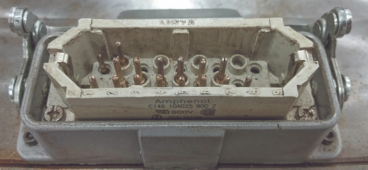
Cables and plugs are a common source of hot runner malfunctions. Here is a connector in which the pin in the upper left corner has been pushed in so that it won’t make proper contact. Photo Credit, all images: Randy Kerkstra
Last month, I discussed how hot runners have evolved dramatically over the past couple of decades, dispelled common myths and reviewed a few often-overlooked areas. This article will provide some hot runner maintenance and troubleshooting tips.
Hot Runner Maintenance Breakdown
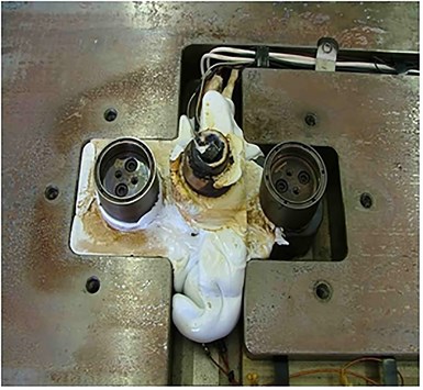
The sight of a hot runner pocket pumped full of plastic is not as common as it was some years back. The biggest contributor to avoiding nightmares like the one shown below was when hot drops started being threaded to the manifold versus relying on the stack height, seal rings and bolt patterns in the mold plates to hold the hot runner together.


Some toolmakers complained from a maintenance perspective that this was more difficult to work on when the drops had to be removed. In some cases, this was true, with threads getting galled up and creating another mess. However, improved thread designs and coatings have reduced this concern for toolmakers. So, in the big picture of hot runner issues, this has been a big improvement from my viewpoint.
I’d like to add a note here about adequate support of the hot half. I have observed some problems in this area over the years, but less so recently. If the areas cleared out for the hot runner are large, just consider ensuring adequate support to reduce the chances of deflection from cavity pressure. I go into a bit more detail on support and deflection in my columns on flash-free molding.
It is also very important when disassembling hot runners to follow proper procedures in removing drops and tips to prevent damage to threads. Proper preheat and torque specs must be followed, especially by less experienced personnel. Fortunately, in most cases of hot runner repairs to clear blockage in the tip or replace heaters or thermocouples, the drop does not need to be removed at all.
It is very important when disassembling hot runners to follow proper procedures in removing drops and tips to prevent damage to threads.
Heaters and Thermocouples
I have also observed that many toolmakers are hesitant to work on hot runners. The sight of numerous wires from the thermocouples and heaters can be intimidating. But in reality, hot runner systems are very simple in design, function and wiring.
Hot runners have zones, typically identified numerically, which are independently controlled with a heater and a thermocouple. It is important to have the wires labeled for each zone so it is easier to troubleshoot versus having to chase wires down among multiple zones. A hot runner schematic should be kept on the side of the tool showing each zone location and the heater wattage.
The power plug/connection and the thermocouple plug/connection are also identified by zones. So, for example, the zone 1 heater leads would be to zone 1 on the power plug, and the thermocouple to zone 1 on the thermocouple plug. The two wires coming off the heater are the same, but on the thermocouple they are not. The thermocouple has a positive and negative wire that must be connected to the correct locations on the plug or it will not function properly. Similar to the plus and minus poles on your car battery, it’s not complicated but will not work if the wires are reversed.
Thermocouples come in different types and colors on the wires. I have mainly used J and K types that usually have red and white wires, but not always. On the J type, the white wire is positive and magnetic and the red wire is negative. If you ever question which one is the positive wire, use a magnet to identify the positive.
If you were to change out a J type with a K type you need to change the thermocouple settings on the controller because they will read an incorrect temperature if used with the wrong setting. There are other thermocouple types that use different colors and will not work properly if your controller is incompatible.
I do not recommend adding wire extensions to thermocouples unless you are experienced with proper methods or wires. Thermocouples are not too expensive, so it’s best to replace damaged ones. Heater and thermocouple connections with extensions must be insulated.
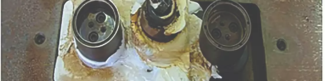
Nasty hot runner leaks like this are a less common sight than they once were. Threaded nozzles are a big reason.
There are some actions you can take to troubleshoot hot runners in the molding machine rather than pulling the mold. One thing I recommend when having hot runner issues is to change out the cables and controller, to take them off the list. Many times I have found the controller or cables to have been the issue. And check the pins in the plugs — at times, they can get pushed in so they are not making contact in the cable plug.
Also, keep in mind that just because the controller shows a zone at the proper temperature does not necessarily mean that it is actually at that temperature. I use a pyrometer with a 0.040-0.060-inch-diameter sheath thermocouple to verify temperatures inside the hot drops or the inlet channel. When verifying temperatures in valve gates, pull the valve pin back to get inside the nozzle flow channel. I gently move the thermocouple back and forth against the steel in the flow channel to get an accurate temperature.
You also need to make actual contact with the steel. You will get a false reading if you just probe inside the drop because the plastic will form a skin on the thermocouple in the flow channel, impacting the temperature reading.
If you find you have a thermocouple issue and are not getting the proper set temperature, most controllers give you the option of running on percentage power output. If you have a matching zone with the same wattage heater, you can set the power percentage to match the amperage draw of the matching zone. You must also consider that the amp draw will change as you are running parts, because the heater will not have to work as hard with hot plastic running through the hot runner.
If you have a zone hotter than the setpoint on the controller, it more than likely is a thermocouple issue. If the thermocouple is loose or not making steel contact with the hot runner or hot drop, it will be reading the air temperature, which would be cooler than the steel of the hot runner. Thus, it is telling the controller the heater needs more amps, leading to a much higher zone temperature than the setpoint on the controller.
If you know the voltage and the watts on the heater you can calculate what ohms that heater should be reading (volts squared divided by the watts equals ohms).
Check Heater Resistance
Heaters are in most cases like a light bulb — either live or dead. But in rare situations, damaged wires with some of the strands broken may not be able to handle all the amps required to bring the heater up to temperature. Heaters can be checked for proper resistance using a multimeter in the ohms setting. If you know the voltage and the watts on the heater you can calculate what ohms that heater should be reading (volts squared divided by the watts equals ohms). For example, if you have a 240-volt heater with 1,000-watt, the ohms should read 57.6 (240 x 240/1,000).
Water leaks — where water gets down into the hot runner system — can also cause problems. With most hot runner designs today, this is not apt to cause major issues with blown heaters like it would with older designs. In most cases, you just need to drain the water and dry the system out and put it back in operation. One sign of a water leak is when zones are struggling or failing to get up to the set temperature.
Valve Gates
Valve gates also add some complexity to the hot runner system. Hence, a little more maintenance compared to a standard hot runner, but nothing to be overly concerned about. The added maintenance involves the valve pins and valve gate seals. For example, removing the valve pins, cleaning any carbon buildup and checking for wear, if you are running material with abrasive fillers. This should be followed by checking the seals on the piston for wear or replacement, then cleaning and regreasing the seals and side walls. You must also use a grease rated for higher temperatures (e.g., Min-Lube from NanoPlas).
I’ve had systems that run 250,000 cycles between maintenance intervals if proper startup and shutdown procedures are followed. The hot runner system you use, the material being molded and startup/shut-down procedures will affect the maintenance frequency based on cycles, not months or time. I prefer to use cycles versus months because each mold runs different cycle counts. I may have one mold that runs 50,000 cycles a year and another that runs 500,000 cycles. So with the first mold, I may do it annually at the most and the second tool a few times a year. It wouldn’t make sense to tear a hot runner apart, which costs money, if there is no need.
It is very important to turn your thermolators on (controls mold water temperatures) before or at the same time you start up a hot runner. If you turn on a valve gate hot runner without the mold cooling on you can degrade the seals and grease on the pistons with the high hot runner temperatures. This can cause failures with valve pin movement.
Updated and republished from Plastics Technology.


Related Content

How to Use Thermal Management to Improve Mold Cooling
A review of common mold cooling issues and possible solutions, including 3D printing applications.
Read More
Laser Welding Versus Micro Welding
The latest battle in finely detailed restoration/repair of mold materials.
Read More
MoldMaking Technology's Most-Viewed Content 2022: Products
MMT shares the five top-viewed technologies, equipment and services of 2022 in each Engineer, Build, Maintain and Manage tenet based on Google Analytics.
Read More
VIDEO: Hot Runner Maintenance Tips
Scott Clark, Hot Runner Business Manager for Husky Technologies, breaks down maintenance practices for hot runner systems.
Read MoreRead Next

Breaking Down Hot Runner Maintenance
Improving a manifold’s maintenance plan requires specific skills and knowledge of its functioning areas.
Read More
Getting Started with Hot Runner Maintenance
Developing basic cleaning and repair skills among in-house technicians should be the goal of every shop that runs hot runner systems.
Read More
Flash Free Molding: It’s about Cavity Surface Area
Randy takes a look at mold areas that can contribute to flash with deflection perpendicular to the machine’s clamp force.
Read More