
Breaking Down Hot Runner Maintenance
Improving a manifold’s maintenance plan requires specific skills and knowledge of its functioning areas.


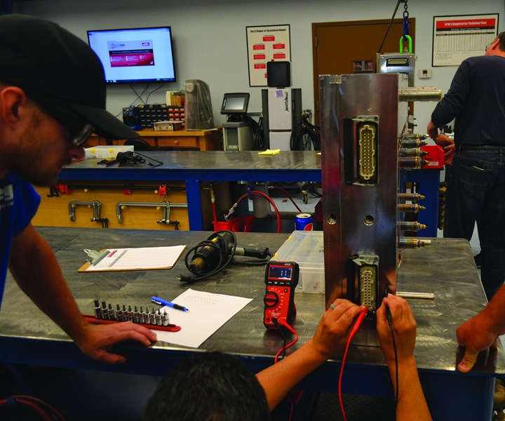
Breaking Down Hot Runner Maintenance (Image 1). Improving a manifold’s maintenance plan requires specific skills and knowledge of its functioning areas. Images courtesy of MoldTrax Maintenance Solutions.
Working on hot runner manifolds requires certain skills and training because of the heat expansion of the steel plates and components. If the mold and repair technician does not understand and cannot account for these effects, he or she may have trouble with mechanics, safety and effective processing. Developing a better maintenance plan for manifold service or repair requires a general knowledge of hot runner systems. That knowledge includes things like the system’s components (fixed or valve gates, heaters, thermocouples, wiring paths), maintenance history, complexity level and required maintenance skills. More importantly, proper manifold maintenance depends upon an understanding of its critical functioning areas (flow paths, seal areas, cooling channels) and its dimensional relationship with the cavities (gates and nozzle tips).
The first step when working on any manifold is identifying the goal of the work, which determines and verifies the specific maintenance plan. For example, is it routine preventive maintenance, or a new or repetitive problem with a mold or part? When it comes to manifolds, the more specific question may be, is preventive maintenance done at an appropriate cycle count? Or, does the PM cycle frequency need adjustment?


Once the shop sets a goal and strategizes a maintenance plan, there are general preparation, disassembly and re-assembly steps to follow for proper hot runner maintenance. These steps are general guidelines when working on most systems. Always check with your hot runner supplier for their recommendations on the proper techniques and sequences.
Preparation Guidelines
- Go to the crib and verify that the necessary tooling is in-house to support the maintenance plan. Necessary tooling includes heaters, thermocouples, nozzles, nozzle tips, valve pins and valve pin bushings.
- Confirm the estimated downtime with the production/molding department.
- Review past maintenance history to determine the most efficient method for mold and manifold disassembly. Most manifolds are removed from the manifold retaining plate in the horizontal position for safety and efficiency, but some are removed more easily in the standing or the vertical position.
- Determine a proper removal procedure for the electrical control box (for example, with nozzle heater and thermocouple wires connected or individually disconnected) and the best disconnection method for the manifold heater wires (for example, disconnected from the manifold or from the control box).
- Identify critical areas and special tools that may be necessary for disassembly. Examples include wooden spacer blocks to carry the manifold weight and to avoid damage to protruding nozzles, rubber caps to protect nozzle tips during manifold removal, eyebolts versus jack screws, a hand lift versus an overhead hoist and a technician’s hands versus a slap hammer for valve pin removal.
- Check all heaters and thermocouples for resistance and shorts using an ohmmeter before disassembly, then record the readings. To do this faster, use a portable hot runner mold testing system, such as the Mold Checker from Fast Heat, which tests hot runner manifolds to ensure that resistances of all thermocouples and heaters are within range.
- Map the position of each thermocouple and heater to verify their connection to the correct pin on the electrical connectors. Record the results (see Figure 1).
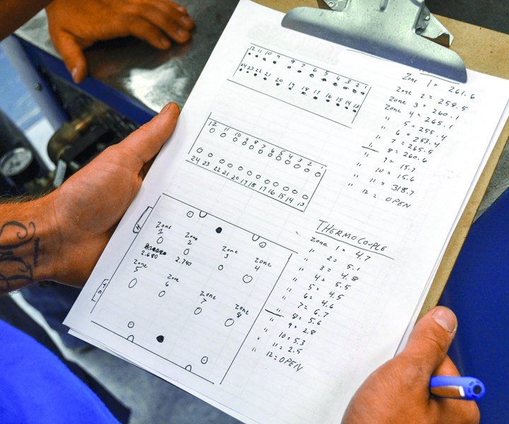
Breaking Down Hot Runner Maintenance (Figure 1). Verify thermocouple and heater connections to the correct pin on the electrical connectors and record the readings/results. Images courtesy of MoldTrax Maintenance Solutions.
Disassembly Guidelines
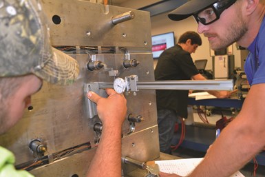
Breaking Down Hot Runner Maintenance (Figure 2). When using a fixed gate system (where there are no valve pins), remove the “A” cavity plate before removing the rear clamp plate to expose the nozzle tips, and measure and record the distance from the nozzle tip to the nozzle plate. Images courtesy of MoldTrax Maintenance Solutions.
- Remove the “A” cavity plate in a fixed gate system (no valve pins) to expose the nozzle tips before removing the rear clamp plate. Then measure and record the distance from the nozzle tip to the nozzle plate (see Figure 2). This dimension is critical to the relationship between the gate area and the land area and can be the root cause of parts that suffer long gate issues (like a spike of plastic sticking out from the gate location). This dimension also serves as a reference point to ensure that the nozzles are positioned correctly after the mold is reassembled.
- Ground the electrical controller directly to the mold, if using a controller to check the heater and thermocouples and if using wooden spacer blocks. The blocks will prevent the mold from being grounded through the steel bench, creating a shocking situation.
- Warm up nozzles to 250°–350°F (depending on the resin) when removing the pins from a valve-gate system. This eases the extraction of the valve pins from the manifold system which prevents the resistance of cold plastic that can damage the valve pins.
- Move the valve pins back or to the open position while they are warm. This prevents damage to the tips on delicate valve pins and protects them if the cavity plate gets jammed on the leader pins and does not come off evenly during its removal.
- Number every tip to a home position for accurate reassembly, so the valve pins take a seat (or running fit) in their related valve pin bushing during production.
- Handle valve pins carefully when removing them, placing them on a bench or in a cleaning basket when cleaning and drying them and when returning to the bench and reinstalling them into the mold. Careless handling will create dings or bend the fragile tips.
- Take additional reference measurements from the manifold plate to the manifold or to any expansion spacers located at the top of the manifold before removing any bolts that are securing the manifold. These measurements help verify that everything was put back together correctly. Measure closest to the corners of the manifold to determine the flatness of the manifold in relation to the manifold plate. If one or more corners varies by 0.010 inch or more, it is likely that the manifold does not sit flat on the nozzles, which points to a potential tooling stack problem.
- Clean and stone an area before taking any measurements. This helps ensure more accurate readings.
- Measure from the top of the bridge to the manifold plate and down to the manifold when a manifold bridge is part of the system. This measurement is useful during reassembly.
- Note wiring routes through the plates and use wire labels to identify the correct heater and thermocouple positions.
- Remove the manifold bolts and carefully lift out the manifold once all the measurements are taken and all the wire clips are removed. If the nozzles are bolted to the manifold plate, removing the manifold might require extra force to break the plastic connection between the nozzles and the manifold feed channels.
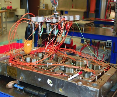
Breaking Down Hot Runner Maintenance (Figure 3). Removing a manifold may require extra force to break the plastic connection between the nozzles and the manifold feed channels, if the nozzles are bolted to the manifold plate. If the nozzles are not bolted to the nozzle plate, they may remain attached to the manifold, as shown here. Images courtesy of MoldTrax Maintenance Solutions.
- Document this procedure with images, as damage can occur if prybars are jammed in the wrong area. If the nozzles are not bolted to the nozzle plate, they may remain attached to the manifold (see Figure 3). At this stage, use extreme caution to ensure the nozzles are not bumped or broken, damaging the tips. Some technicians prefer to pull the manifold while it is hot, which helps to break the nozzle/manifold connection. Wear proper gloves and other appropriate gear when using this method.
- Clean all tooling carefully. Do not haphazardly pile valve pins and other delicate components into a single steel cleaning basket.
- Make sure there is no plastic or residue at the sealing points located at the junction of the plastic flow paths.
Re-assembly Guidelines
- Be careful using soft brass, aluminum or copper tools during reassembly, as they easily flake or chip. These chips can fall into areas that cause sealing problems and slow leaks.
- Use the right tool for the right job to avoid excessive force for reinstalling the tooling. Stop and identify the cause of any resistance before breaking out the big hammer.
- Work methodically during reassembly. Do not forget to install bolts, dowels and spacers, as this will require the manifold to be disassembled again. Remember that manifolds fail because of the way we put them together, not because of the way we take them apart.
- Read the feedback from your hands and tools. For example, some root causes of manifold leaks include nozzles that fit tightly into bores, manifolds that rock (or do not sit flatly) after being reset onto nozzles and dowel pins that are not properly lined up or engaged.
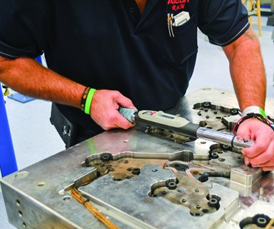
Breaking Down Hot Runner Maintenance (Figure 4). Use a standard torque setting for the bolt size and a balanced, corner-to-corner pattern to torque manifold bolts if the manufacturer specifications are not available. Images courtesy of MoldTrax Maintenance Solutions.
- Torque the manifold bolts to manufacturer specifications. If those are not available, then use standard torque settings for the bolt sizes in question. Use a balanced, corner-to-corner pattern if a manufacturing torque pattern is not available (see Figure 4).
- Use an anti-seize product on the bolt threads and under the head to prevent waste in torque force. Technicians often waste as much as 30 percent of torque force to overcome friction.
- Re-heat nozzles to ease installation if installing valve pins.
- Test manifolds, nozzle heaters and thermocouples with an ohmmeter or a portable hot runner mold testing system before bolting it onto the back-clamp plate.
- Recheck heaters and thermocouples for shorts and connectivity issues after the clamp plate is reinstalled and tightened, and then document the readings.
- Make sure there is no variation in temperature between the cavity plate and the nozzle plate when installing a cavity plate to a nozzle plate or working on manifolds in the press while changing or cleaning nozzle tips. For example, a 25-degree difference in temperature could cause the center-line distance of the nozzles to be off by 0.004 inch over 24 inches in relation to the cavities, resulting in misalignment between the cavities and nozzle seals. This will damage the seals and cause slow, catastrophic plastic leaks.
- Document all issues throughout maintenance, such as poor wiring conditions, wire pinch points, worn electrical connectors, stripped threads and damaged electrical boxes. Take pictures along the way for future reference.
- Create and use maintenance manuals to advance the team’s knowledge base about the most appropriate, efficient and safest methods to use when working on a specific manifold system.
Although working on hot manifolds is an area of mold maintenance that requires a
bit more knowledge, focus, patience and hand skills, these general preparation, disassembly and re-assembly guidelines will help structure and simplify a hot runner maintenance plan. The key is being proactive, creating a data-driven shop environment and encouraging continuous improvement across the toolroom.
New Techniques Prove Benefits of Proactive Hot Runner Care
By Cyndi Kustush,Senior Editor, MoldMaking Technology
Jeremy Dykes is the general manager of Millennium Tool Inc. (Louisville, Kentucky). He describes the Hot Runner Maintenance and Repair Certification course offered at MoldTrax as “eye-opening.” Millennium Tool Inc. (MTI) is a provider of engineering changes and repair/maintenance services for molds, dies and fixtures. In 2010, the company set up a team of 32 mold and die maintenance and repair technicians and moldmakers at a General Electric Appliances molding facility. The crew oversees maintaining and repairing stamping dies and injection molds. The molds are 200–3500 tons. Dykes leads the team.
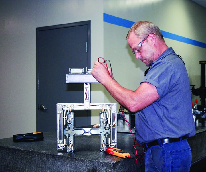
New Techniques Prove Benefits of Proactive Hot Runner Care-Sidebar. The Millennium Tool Inc. team learned how to use the ohmmeter to monitor the hot runner systems and chart the resistance levels so that they can proactively repair or replace these components before there’s a larger problem. Image courtesy of Millennium Tool Inc.
“We oversee about 1200 different tools, 60 percent of which are injection molds with different brands of hot runner systems,” he says. His background as a toolmaker mainly centered on stamping dies. Dykes had limited experience with injection mold hot runner systems and how to maintain them, so he enrolled in courses at MoldTrax, including its hot runner maintenance and repair class. That was two years ago. Dykes says the class gives such a quick return on investment (ROI) that he has already sent several of his team members to the training and intends to send more. “Some of them have been doing this kind of work for 20 years and thought they would be bored, but they learned new and useful techniques. They were very impressed,” Dykes says. “The ROI is that more team members are skilled in the art and science of hot runners. We no longer have to rely on two or three team members to do all the hot runner work. The wait to get a qualified person available has been cut in half.”
An example of those new techniques came into play when dealing with one of the team’s recurring challenges—bad hot runner heaters and thermocouples. “We learned how to use the ohmmeter to monitor the hot runner systems and chart the resistance levels so that we can proactively repair or replace these components before there’s a larger problem. Our goal is to perform preventive maintenance, as opposed to working on the tools in the presses once something goes wrong,” Dykes says.
Dykes and his team also learned about valve pins and how critical it is to time them out, fit them and so on. In addition, they learned to use advanced controllers to heat manifolds to the processing temperature to ensure that valve pin heights are set to specifications. MTI implemented this process at General Electric right away, he said. They also purchased a new controller with more features to replace an outdated and less-equipped system. “The new controller has the ability to do diagnostics on bad heaters, thermocouples and zones, and will signal any errors or shorts within the hot runner system when plugged into the thermocouple and heater boxes. It also allows us to save thermocouples to run two drops off of one zone. It’s important to have a good controller to measure the status of the whole system.”
Dykes says there have been investments in other equipment, too, that have significantly impacted the overall hot runner repair and maintenance process. They use two Cold Jet dry ice cleaning systems, for example, to clean molds. They also use hot runners in instances where removing resins is difficult in comparison to other methods, like solvents, scrapers, stones and so on. Dykes also plans to purchase an ultrasonic cleaner by the end of the year.
More than anything, the hands-on aspect of training at MoldTrax really ingrained the theory behind systemized hot runner maintenance for Dykes and MTI. “Before, we were in major fire-fighting mode, working based on hand-to-mouth experience and learning the hard way,” Dykes says. “Today, we’re working more efficiently; we’re keeping important spare parts on hand, and we’re no longer waiting for failures to happen. The class showed us the importance of being proactive in the repair and maintenance of hot runner systems so they will perform at optimal levels.”
About the Contributor
Steve Johnson
Steve Johnson is the president of MoldTrax, which provides specialized course work, hands-on bench training, maintenance software, maintenance products, toolroom design and maintenance efficiency auditing.
More hot runner essential reading:
Switch to Hot Runners Pays Off for Pulley Molder
Six Key Factors for Evaluating a Hot Runner System
7 Key Advantages of Hot Runner Systems


Related Content

Machining Center Spindles: What You Need to Know
Why and how to research spindle technology before purchasing a machining center.
Read More
The Benefits of Hand Scraping
Accuracy and flatness are two benefits of hand scraping that help improve machine loop stiffness, workpiece surface finish and component geometry.
Read More
Hands-on Workshop Teaches Mold Maintenance Process
Intensive workshop teaches the process of mold maintenance to help put an end to the firefighting culture of many toolrooms.
Read More
How to Eliminate Chatter
Here are techniques commonly used to combat chatter and guidelines to establish a foundation for optimizing the moldmaking process.
Read MoreRead Next

Six Considerations for Evaluating a Hot Runner System
Details matter when it comes to selecting and integrating a hot runner system. This guide makes that process easier by covering those details thoroughly.
Read More
Why Choose a Valve-Gated Hot Runner?
Moldmakers need to be aware of how different gating technology can affect their customers when designing a hot runner system into a mold.
Read More
How to Use Strategic Planning Tools, Data to Manage the Human Side of Business
Q&A with Marion Wells, MMT EAB member and founder of Human Asset Management.
Read More