


Figure 1: Side locks provide for a small degree of early engagement protection depending on the particular profile. Figures courtesy of PCS Company.
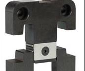
Roller bearing lock. Image courtesy of PCS Company
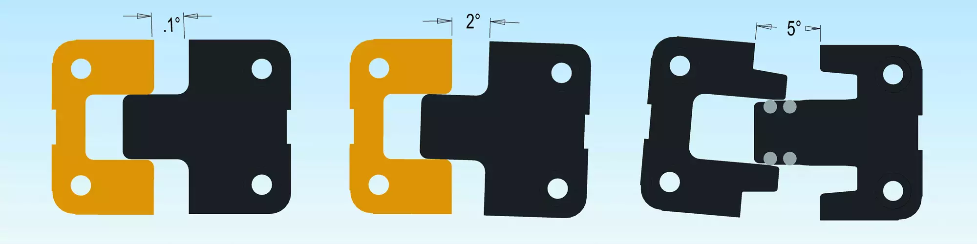
Determining early engagement of standard straight and tri-lock.
Molders, moldmakers and mold designers should all take a stake in the decision-making process when it comes to choosing the proper alignment mold lock. Choosing the correct alignment lock can reduce maintenance expense and molding downtime, as well as increase part quality over the entire life of the mold. Make your lock choice carefully. Alignment and mold lock-up is a crucial function of any mold. Stationary and movable mold halves, slides and lifters must align to ensure consistent plastic molded part quality. This is where alignment locks come in to play.
Alignment is usually the function of the leader pins and bushings. Typically, leader pins and bushings have sufficient clearance to avoid binding and seizing between .0015 to .003, and additional clearance with accumulative tolerance. For most molds, this is not sufficient, requiring additional locking components to ensure location under injection molding melt pressures and to maintain consistent molded part thickness.


Lock Types
There are three basic types of alignment locks:
1. Tapered with variations of bar and round
2. Straight with variations of side, top and needle bearing
3. Combination taper straight and roller bearing with variations of side and top1
1. Tapered Locks
Tapered bar locks are primarily used to prevent core shift during injection melt. All tapered bar locks typically use a non-locking taper greater than 7 degrees, with most locks using a 10-degree taper per side. The long rectangular bar with large locking contact does not provide early alignment for protection of cores, and the mold must be completely closed to provide an accurate location. Before installing bar locks, you must also consider thermal expansion. A 10°F difference at 24 inches will cause a .0015 inch interference. Depending on the temperature and size of the mold, interference can be even larger. Tapered bar locks should always be installed parallel to the expansion. This puts limits on the flexibility of installation location.
Tapered round locks are usually used as locators only. As with tapered bar locks, they do not provide early alignment or protection of cores, and thermal expansion must also be considered because of the 360-degree contact area. Tapered round locks are usually not recommended for mold bases with a large distance between locators. Tapered round locks are recommended for use in mold inserts when the distance between locaters is small, minimizing thermal expansion.
Determining early engagement of standard straight and tri-lock. Photo Credit, all images: PCS Company
2. Straight Lock Variations
Straight locks are the most widely used lock in the industry. Designs are virtually identical between all manufacturers with the exception of material, coatings, grease grooves and graphite plugs. Straight locks were designed to eliminate the thermal expansion problem, allowing the locks to move freely in one direction while maintaining location on the opposite direction. Installing four locks will ensure the mold is always on center regardless of the temperature differential between the two mold halves. The basic design has a male and female component, each having a few ten thousands clearance per side.
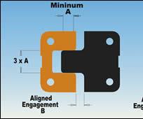
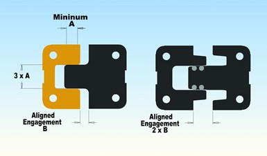
Standard side locks are used to create lock-up location, which helps overcome injection melt pressures. Side locks provide for a small degree of early engagement protection depending on the particular profile (see Figure 1). Side locks are typically machined on the centerline axis, both vertically and horizontally on the outside of the mold. Side locks require the least amount of space for installation. Machining lock pockets should be done with both halves clamped together to ensure parallel location between mold halves. Generally, side locks can easily be installed in a precise accurate location.
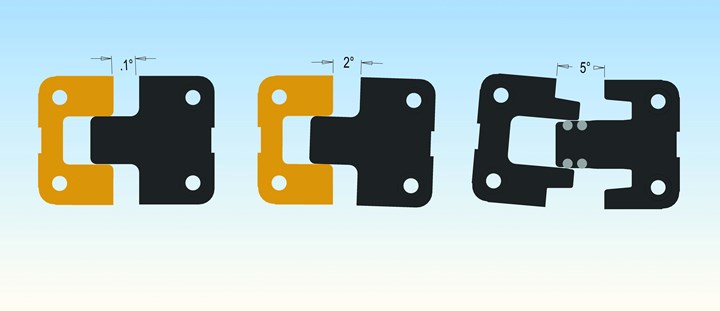
Figure 1. Side locks provide for a small degree of early engagement protection depending on the particular profile.
Like side locks, standard top locks provide lock-up location to overcome injection melt pressures with a small degree of engagement protection. Top locks are typically machined on the centerline axis, both vertically and horizontally from the face of the mold. Top locks should be machined at the same time as the leader pins and bushings to ensure parallelism and proper location relative to the leader pins. Unlike side locks, top locks are machined in two separate setups, requiring a high degree of machining precision.
Needle bearing locks attempt to address some of the shortcomings of the standard straight lock design, specifically initial engagement. The single point radial contact provides a non-binding lift to align a sagging mold, which is an effective alignment method. Needle bearing locks provide some early engagement protection, but they can fall short of molder expectations when trying to overcome injection melt pressure in final lock-up with single point contact. Simply put, the strength is not there.
Although straight locks are considered an alignment component, they rely on the leader pins and bushings to align the mold, and function as a locking device. In a perfect world, when the tool is new with concisely machined square parting line pockets, new leader pins and bushings, and a new molding machine with perfectly square platens, the standard straight locks work flawlessly. However, in the real world where even new molds are subjected to molding machines with worn tie bars and bushings, molds tend to sag and lean down and forward under their own weight. Leader pins alone are incapable of providing a suitable location to provide a smooth entry into a straight lock that only has .0002 ten thousands clearances, causing an interference fit (see Figure 1). A one tenth degree misalignment will cause a .00022 interference. A 2-degree misalignment has .0072 thousands interference, thus guaranteeing a seizing and binding problem.
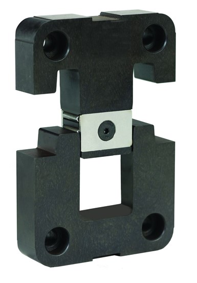
Roller bearing lock.
3. Combination Straight, Taper and Roller Bearing Alignment Locks
The best of all worlds, the roller bearing lock is a proven, patented combination alignment lock that combines the best features of the tapered, straight and needle bearing locks with additional benefits.
Starting with the first phase of initial alignment, the roller bearing lock uses large hardened rollers and a lift radius on the female side that creates an effortless engagement even when a large mold misalignment exists.
In the second phase, the roller bearing lock alignment provides maximum early engagement protection, up to two times the length of standard straight and needle bearing locks with the same physical size.
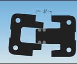
The third phase is final lock-up holding strength. The male side has a 5-degree taper with over travel protection, assuring the tightest tolerance, maximizing holding strength.
Roller bearing locks require the same machining as standard straight locks and, in many cases, have the identical footprint, making substitution easy. The roller bearing lock design symmetry enables full interchangeability between male and female components. The superior design and long life expectancy of the roller bearing lock permits a limited one-million cycle warranty. 2
The roller bearing lock is available for both side and top applications with these benefits:
- Effortless misaligned initial engagement
- Longest early engagement protection
- Highest possible lock-up strength
- Potential for identical footprint to current lock
- Interchangeable male and female components
- .000 interference, even at 5-degree misalignment, eliminating the issue of seizing and galling
- Reduced maintenance expense over the life of the mold
Summary
Regardless of your alignment needs, there are several factors that must be considered before the proper lock can be chosen: condition of your molding machine; condition of your mold; and level of importance for minimizing mold maintenance expense, minimizing molding downtime, consistent mold part quality, smooth friction free engagement, early engagement and tongue length; and long term lock-up strength.
References
- Tri-Lock from PCS Company.
- PCS Company warranty details.


Related Content


3D Printing Enables Better Coolant Delivery in Milling Operations
Just like 3D printing enabled conformal cooling channels in molds, additive manufacturing is now being used to optimize coolant delivery in cutting tools.
Read More
How to Eliminate Chatter
Here are techniques commonly used to combat chatter and guidelines to establish a foundation for optimizing the moldmaking process.
Read More
The In's and Out's of Ballbar Calibration
This machine tool diagnostic device allows the detection of errors noticeable only while machine tools are in motion.
Read MoreRead Next

Lean Manufacturing Trims Leadtimes
Moldmakers aren't the only ones reducing leadtimes. Component and hot runner suppliers are delivering their equipment and supplies faster to accommodate industry demand.
Read More
How to Use Continuing Education to Remain Competitive in Moldmaking
Continued training helps moldmakers make tooling decisions and properly use the latest cutting tool to efficiently machine high-quality molds.
Read More
Are You a Moldmaker Considering 3D Printing? Consider the 3D Printing Workshop at NPE2024
Presentations will cover 3D printing for mold tooling, material innovation, product development, bridge production and full-scale, high-volume additive manufacturing.
Read More