Share
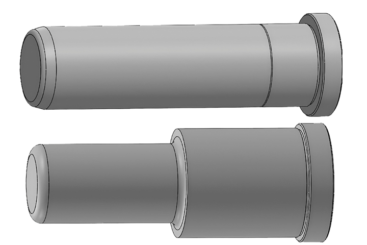
Figure. 1 Straight (top) and shouldered (bottom) leader pins. Photo Credit, all images (including landscape image): Jim Fattori
Leader pins are often referred to as guide pins. They lead or guide one half of a mold into the other. The outer diameter of a leader pin is typically 0.0010 inch below nominal with a tolerance of +0.0000/-0.0005 inch. A leader pin bushing typically has an inside diameter of 0.0005 inch above nominal with a tolerance of +0.0005/-0.0000. Therefore, the pin has a close sliding fit in its mating bushing with a clearance of between 0.0015 and 0.0025 inch total. A close sliding fit is intended for the accurate location of parts that must assemble without perceptible play.
I must admit, I was only vaguely familiar with the nomenclature of a few of the many types of fits. With the possible exception of those of you who design high-cavitation, unscrewing or multiple interchangeable molds, most designers rarely, if ever, need to know the various definitions, specifications and use of the various types of fits.
In fact, I frequently see 2D paper drawings on the toolroom floor with the annotation “fit,” which leaves the dimensions and tolerances up to the toolmaker. Molds that require the toolmaker to adhere to toleranced drawings will cost more due to the additional time to measure and adjust the dimensions of the mold components. Regardless, it is well worth taking some time to become familiar with the various types of fits, if for no other reason than to use the correct terminology when speaking with others. The major categories of ANSI B4.1-1967-R1987 fits are:
- Running or Sliding Fits (RC1 through RC9)
- Locational Fits (LC, LT, LN)
- Locational Clearance Fits (LC1 – LC11)
- Locational Transition Fits (LT1 – LT6)
- Locational Interference Fits (LN1 – LN3)
- Force or Shrink Fits (FN1 – FN5)
The majority of leader pins offered by mold component suppliers include a small shoulder at the head end, which is 0.0010 inch above nominal with a tolerance of +0.0005/-0.0000, as shown in Figure 1 (top). The purpose of this oversized shoulder is to provide an interference fit at room temperature in a mold plate — typically a medium or heavy drive type of fit. Technically, the amount of interference should be proportional to the diameter of the pin and the amount of desired pressure to install, as per one of the ANSI class ratings, but that is basically overkill for our application.
Still, you need to keep in mind that pin and bushing sizes and tolerances are catalog specifications. To avoid any unwelcome surprises (I’ve heard a couple of troubling reports about some suppliers’ products), it is imperative that you measure every pin to four decimal places prior to machining the holes in the mold base — just like you should be doing for ejector pins and sleeves.
Measure all pins prior to installation.
If you ever receive pins or bushings that are out of specification, you have three options: You can ask that they be replaced; you can return them for credit (usually accompanied with a nasty letter or email); or you can machine the bore holes in the plate according to the actual pin dimensions. If you choose this last option due to the required mold delivery date, be sure to number the pins so they are re-installed in the corresponding holes during any routine maintenance.
The length of the oversized shoulder varies with the pin’s diameter and length. They are usually adequate for most molds. But say, for example, you have a leader pin mounted in a 23/8-inch-thick plate, but the shoulder is only 7/8-inch long. Some moldmakers prefer this small amount of bearing surface because it makes the pin easier to install and remove — like relieving the sides of a cavity insert.
Other moldmakers go to the other extreme: They grind the shoulder off the pin and machine the bore hole in the plate 0.0010 inch undersized. They feel it is more important to have the interference portion run all the way up to the parting line, even if it requires a few more blows with a mallet to install or remove. If the bearing length is extremely long, the press or driving type of interference fit may end up being a force drive or shrink fit, which can require freezing the pins and heating the plate to install them. Regardless of the amount of interference, a little bit of oil will go a long way during assembly.
It is not uncommon for the opposite condition to occur — where the length of the oversized shoulder is longer than the thickness of the plate. In this case, the portion of the shoulder that extends past the plate should be ground off, so as not to interfere with the fit in the bushing.
Leader pins are also available in a shouldered or stepped version, as shown in Figure 1 (bottom). The diameter of the shoulder is the same as the outer diameter of its mating bushing. These pins allow the mold base to be “line” or “through” bored — at the same diameter, in the same location, at the same time and with the same precision — by stacking the plates together. The shoulders of shouldered leader pins are 0.0010 inch above nominal, with a tolerance of +0.0005/-0.0000 for a medium to heavy drive fit in the mold plate.
The oversized portion of the pin is the entire length of the shoulder and varies with the pin diameter and length. While shouldered leader pins have several advantages, they are not often used today, thanks to the precision of modern CNC machines and the advances in cutting tool technology, which typically result in dimensional tolerances of ±0.0010 inch or less. The added step of jig boring or jig grinding the bore holes after machining, to obtain accuracies less than half that amount is now reserved only for the most demanding molds. And that makes sense. While leader pins and bushings provide fairly accurate initial alignment of the mold plates, it is the parting-line interlocks that provide the final and most precise alignment.
Many moldmakers purchase off-the-shelf mold bases, which allow them to focus on making the cavities and cores. This helps reduce the lead time of the mold, as well as eliminate the need to have expensive milling and grinding machines capable of handling large plates. Thanks to standardization, many mold bases can be shipped within a week. The leader pins supplied with these mold bases are usually mounted in the A-plate and extend into the B-plate. Sometimes they extend a little past the B-plate when the mold is closed; sometimes they don’t. It all depends on the manufacturer and the type of mold base. But is that what you need for every job?
Leader pins are not only supposed to initially align the mold halves during closing, but they should protect the cores in the event of poor alignment. In my opinion, if the cores are taller than the exposed portion of the leader pins, the leader pins are too short. I prefer leader pins that engage their bushings a minimum of ½ inch before the cores begin to enter their cavities, and before any angle pins enter their cams.
Many of you may think this is completely unnecessary. But picture this scenario: A mold is installed in a machine one half at a time, due to its weight or size. After the setup man installs the first half, he accidently installs the second half upside down. I’ve seen this happen on more than one occasion. If the leader pins are not long enough to protect the cores when the mold closes, it can be a very costly mistake.
My preference is to always try to mount the leader pins in the B-plate on the core side, with the bushings on the cavity side. When the mold is open on the workbench, the leader pins also protect the cores from damage in the event the plate tips over. This is fairly common when the center of gravity is unbalanced. However, other factors, such as part ejection (automatic, manual or robotic), can dictate on which side the leader pins should be installed. All four leader pins do not necessarily need to be installed on the same side of the mold. Nor do they all need to be the same length or diameter. Nor does there need to be four of them. There is no problem mixing and matching any of these factors if it overcomes a particular problem or suits a particular need — regardless of how out-of-the-norm it looks.
So far, I have been referring to leader pins in simple two-plate molds. However, when a mold has more than one parting line, the leader pins take on an added role. In addition to the initial alignment of the fixed and moving halves of the mold, they must now support the weight of one or more floating plates. This requires additional design considerations to be made. The four primary considerations are pin length, diameter and orientation, as well as bushing relief.
Stripper-plate molds (often called five-plate or six-plate molds), and many floating-plate molds (often called six-plate or AX-series molds), typically have the leader pins mounted on the ejection side to support the stripper plate or floating plate. Three-plate molds (often called T-Series molds), have the leader pins mounted on the injection side — to support the floating X-1 plate and the A or X-2 plate. Ideally, the leader pins should be engaged in their bushings at least ½ inch when the mold is fully open. This is not always possible without using very thick plates, increasing the height of the ejector housing or adding spacers on the back of the ejection clamp plate — all of which increases the stack height and the cost of the mold.
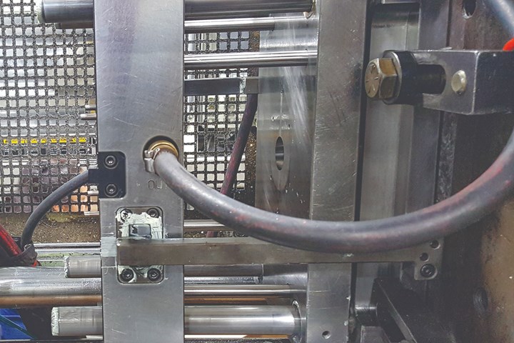
However, the goal is obvious: to support both ends of the leader pins so that they can support heavy plates without deflecting downward. Leader pins with good support are particularly important when the stroke of a floating plate is long, which increases the cantilevered forces on the end of the pins, as shown in Figure 2. This is when larger diameter leader pins are often required to reduce the amount of deflection. Otherwise, you may hear that all-to-familiar banging sound when the mold starts to close, because the leader pins do not precisely align with their bushings. That’s a great way to make the bushings deform, gall or prematurely wear out.
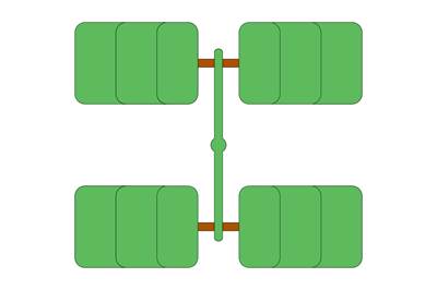
If you decide to increase the diameter of the leader pins, you will need to move their location inward because there will be insufficient steel between the outer diameter of the pin and the exterior faces of the mold. An alternate method is to add a second set of leader pins and bushings facing the opposite direction. When the mold is in the full open position it has eight pins engaged in the floating plate, instead of just four.
Use caution when selecting leader pins for molds with multiple parting lines.
All floating plates will have leader pin bushings in them. The length of these bushings is often the same as the thickness of the plate. The problem is some plates are notoriously thin. For example, the X-1 plate in three-plate molds are typically only 7/8 - or 1 3/8 -inch thick, even for molds as large as 35 × 23 3/4 inches. These plates can often cock and bind during assembly, as well as in production. It is often warranted to have the bushings in these plates longer than the thickness of the plate to provide additional alignment. Obviously, clearance for the extended length needs to be accounted for in the adjoining plate.
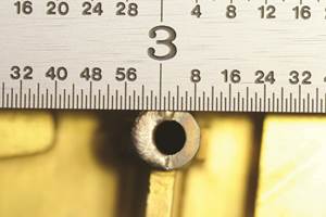
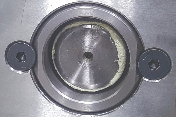
Bushings in floating plates need to be retained by some means because there is nothing to prevent them from sliding out over time. Flat-head screws on a parting line are one common retention method, as shown in Figure 3. My preference is to use one of the various types of retaining rings. They can be the internal type, installed in a groove in the bushing’s bore hole, or the external type installed in a groove machined in the OD of the bushing. I have seen several molds with setscrews installed from the sides of the mold. Unless there is a groove machined into the bushing and the setscrew doesn’t apply any lateral pressure, this is not a good method to use.
Also keep in mind that many types of bushings have relieved bores on the shouldered end. Depending on the length of the bushing, the amount of relief can be as much as two inches. This can affect your decision on which way to orient the bushings in a floating plate mold, and how long the leader pins need to be to obtain the maximum support and guidance.
Some molds do not have their cavity or core inserts mounted in pockets. Instead, they are bolted directly onto the front face of the A- and B-plates. This type of mold design is called “face-mounted.” One issue often associated with face mounting is that the leader pins do not reach their bushings. You have a couple of options to rectify the situation. If you only need to reduce the distance between the leader pin and the bushings by an inch or two, you can install bushings used for stamping dies, which are also face mounted, as shown in Figure 4 (top). Alternatively, you can add spacer blocks or risers to retain standard bushings, Figure 4 (bottom).
Like any two sliding components, the softer component will wear or initiate galling first. So, what is the best type of bushing to use for leader pins? That depends on several factors, such as cost, cleanroom considerations, the intended lifespan of the mold and your personal preference. Instead of rehashing the various types here, I refer you to my October 2020 column on guided ejection systems. Guided ejection bushings share many of the same functions as leader pin bushings. In addition to all the types mentioned in that article, a new type of bushing has since emerged in the market. It is a hardened steel bushing with an infused black nitride treatment and a surface hardness of 66 to 70 Rockwell C. Even though these bushings are reportedly able to run without lubrication, they have internal grease grooves for added protection.
Many of the molds built in Asia have grease grooves machined into the leader pins, as shown in Figure 5. I’m not a fan. The bushings are the component that should have the grease grooves, to help avoid getting grease on the molded parts, as shown in Figure 6. This brings up an important point for those of you who purchase molds offshore — or even domestically. It would be prudent to specify the cavities and cores are made of tool steel from a familiar and reputable supplier, especially if they are to be heat treated.
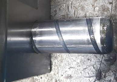
Figure 5. Leader pin with spiral grease groove.
It would also be prudent to specify the desired brand of the various mold components, such as pins, sleeves, bushings, interlocks, etc. Avoid allowing “equivalent” brands to be used because your idea of equivalent, and their idea of equivalent can be two vastly different things. I can’t stress enough just how important this is.
Thermal expansion can occasionally cause a problem for leader pins and bushings. It can be the reason why a mold won’t close under low pressure. For the sake of example, let’s say a mold is 35.5 inches long and the processor deems it necessary to run the cavity 30°F warmer than the core to prevent the parts from sticking. The coefficient of thermal expansion (CTE) for tool steel is approximately 6.5 x 10⁻⁶/inch/inch/°F. (Actually, it ranges from 5.6 to 7.6 × 10⁻⁶, depending on the type of steel.) Therefore, the amount of thermal expansion over that 35.5 inches will be about 0.007 inch total, or 0.0035 inch from the centerline of the mold. The clearance between a leader pin and its bushing is between 0.0015 and 0.0025 inch. See the problem? If the setup man decides to solve the problem by switching the clamp into high pressure, you should check for bent leader pins or bushings that are now sitting in egg-shaped holes.
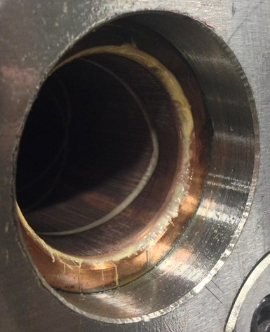
Figure 6. Bushing with internal grease grooves.
I once saw a mold that had flats ground on the leader pins. They were about 0.005 inch deep, spaced every 45° apart. This was an odd, but semi-clever way to vent the pins to avoid that vacuum popping sound when the mold opens. A better and more customary method is to add cleanout slots under the leader pin bushings. These slots serve two functions, the first being to let air in and out to avoid the vacuum condition, as well as to avoid a pressure condition, which will pump the grease out.
The second function is to provide a place for the extra grease and debris to escape the mold. Instead of adding cleanout slots, consider making them cleanout ramps. Basically, they are slots cut on an angle to help ensure debris is discharged out of the mold. No matter what type of slot you add, it is important to consider the orientation of the mold when it is hung in the press. Debris will not defy gravity, especially in the two slots at the top of the mold if they are facing the ceiling. At the very least, they need to face the sides of the mold. Obviously, the slots on the bottom of the mold work best when facing the floor.
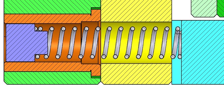
Figure 7. Spring-loaded debris guard inside a bushing.
Small parts with some type of undercut on them tend to fly off the cores during ejection. The parts can accumulate inside the leader pin bushings and create a problem over time. An air blast can usually solve the problem, but compressed air is expensive, and the intended result is not always guaranteed. One trick is to add a light-duty compression spring, pushing a plastic plunger inside the bushing(s), as shown in Figure 7.
Updated and republished from Plastics Technology.
Related Content
Maintaining a Wire EDM Machine
To achieve the ultimate capability and level of productivity from your wire EDM on a consistent, repeatable and reliable basis, regular maintenance is a required task.
Read MoreSolving Mold Alignment Problems with the Right Alignment Lock
Correct alignment lock selection can reduce maintenance costs and molding downtime, as well as increase part quality over the mold’s entire life.
Read MoreHands-on Workshop Teaches Mold Maintenance Process
Intensive workshop teaches the process of mold maintenance to help put an end to the firefighting culture of many toolrooms.
Read MoreLaser Welding Versus Micro Welding
The latest battle in finely detailed restoration/repair of mold materials.
Read MoreRead Next
Save Time, Money: Use a Mold Design Checklist
Here are 15 examples of common molding issues that occur during an initial mold trial. Many of them could be avoided or corrected with a proactive checklist.
Read MoreBest Practices for Hitting Critical Numbers: Communication and the Shrinkage Factor
Start with an upfront review, discussion and collaboration with the customer and then consider the shrinkage factor.
Read MorePenn Erie Tooling Division General Manager Shares Three Favorite Articles: People, Pins and Passing It On
MMT’s Editorial Advisory Board shares its top MoldMaking Technology articles and how this content has been valuable to their businesses.
Read More











.png;maxWidth=300;quality=90)



_300x250 1.png;maxWidth=300;quality=90)

