

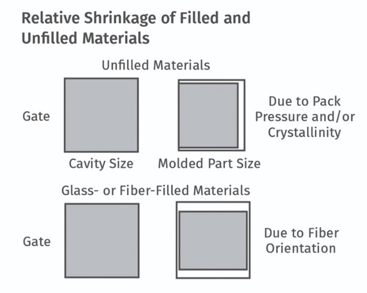
If the material is glass or fiber filled, the anisotropic shrinkage will be less than for unfilled materials, but the difference between the two directions is considerably greater and the directions are reversed—much less shrinkage in the direction of flow and much more perpendicular to the direction of flow. Photo Credit: Injection Mold Consulting LLC
The biggest tooling problem I know of has little to do with cutting steel. The problem is failing to consider, obtain and verify all the pertinent information up front to ensure the mold will produce a dimensionally, functionally and aesthetically acceptable part.
The customer supplies a toolmaker or molder with a 3D solid model and a 2D drawing and says, “Build me a mold to produce parts as per the supplied drawings.” Cutter paths are generated from the solid model, but parts are inspected to the 2D drawing. How do you know the 2D and 3D information is identical? Even though a good 3D CAD program can automatically update the 2D drawing, it can’t change the revision level and print itself out. Additionally, since dimensions on a 2D drawing can be manually overridden, the final, or “Released for Production” 2D drawing, should be checked to ensure it matches the 3D model.


Two-dimensional drawings can have anywhere from three to 300 dimensions on them. Part designers often leave out the critical tolerances or neglect to adjust the precision of each dimension to what is actually required. The industry standard of linear dimensions are specified to three decimal places, radii to two places and angles to one place. But on occasion, you will see a complex threaded closure with dimensions drawn to two-place precision, or a simple pet toy drawn to four-place precision. It’s what makes our jobs interesting.
The title block in the corner of the part drawing specifies the generic tolerances based on the precision of a dimension—typically ±0.005 inches for three-place dimensions. While ±0.005 is not a problem for the tool maker, it can be a real challenge for the molder. And if the molder can’t hit the numbers, fingers usually get pointed back at the tool maker.
Unless you’re molding something as small and precise as a detonator cap for an airbag, the majority of the dimensions on a drawing usually don’t need to be held to within 0.005 inch. The customer should identify the truly critical dimensions that affect the form, fit and function of the part. The critical dimensions should then be evaluated to see if specific areas of the mold can be made “steel safe” by leaving on extra steel or by installing an insert, in case adjustments need to be made after the initial sampling to bring the part into spec. These additional machining and resampling costs should be included, if not noted as a separate line item, on the mold quotation.
Draft and Notes
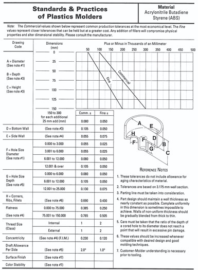
Figure 1: The Plastics Industry Association’s Standards & Practices of Plastics Molders offers Molding Guidelines that list “commercial” and “fine” tolerances based on material type and part size. Photo Credit: The Plastics Industry Association’s publication, Standards & Practices of Plastics Molders.
Almost all thermoplastic materials shrink when they transform from a liquid state to a solid state. Let’s say you are molding a part 0.125 thick × 0.5 wide × 5 inches long and the material shrinkage percentage is 0.50% (or a shrinkage factor of 0.005). Note: The shrinkage factor is a unit-less number, such as mm/mm or mile/mile. The thickness of the part will theoretically shrink 0.0006 inch, the width 0.0025 inch and the length 0.0250 inch. Obviously, the larger the dimension, the greater the total amount of shrinkage. Toolmakers and molders know this all too well. Many customers and part designers don’t—especially if their background is in metal fabrication. A drawing may have a large part dimension, such as 15 inches with a 0.005 inch title-block tolerance. That’s probably not going to happen. This needs to be explained to the customer.
The Plastics Industry Association has an excellent publication entitled “Standards & Practices of Plastics Molders.” The section on Molding Guidelines lists “commercial” and “fine” tolerances based on material type and part size (see Figure 1).
Our business is full of risks. The more steps we take up front to minimize these risks, through the joint collaboration of the concerned parties, the more competitive and profitable we will be. And those are the most important numbers to hit.
The American Society of Mechanical Engineers’ Y14.5-2009 standard is considered the authoritative guideline for geometric dimensioning and tolerancing (GD&T). Unfortunately, many part designers don’t use GD&T nomenclature on their drawings (see Figure 2). But that doesn’t mean characteristics such as straightness, flatness, concentricity and position aren’t important to them.
Drawing notes such as “Part to be free of flash and sharp edges” or “Trim gates flush” need to be taken seriously because they may require a secondary operation. The only thing worse than stringent notes like these are no notes at all. Aesthetic parameters are rarely defined on a drawing and yet are always important. A customer once told me, “I don’t care about weld lines, sink, flash or gloss. They don’t affect the function of the part. But I have to put it on a purchasing agent’s desk and convince him my parts are better.”
Don’t dismiss cryptic notes such as, “Must conform to XYZ Company specification #SP-4265 and mate with P/N 3127.” If the customer neglects to provide the relevant information, mating parts, etc., that may not exonerate you if the parts don’t function properly.
Check to see if the draft angles are specified in the correct direction and are sufficient to release the part from both the cavity and the core, especially if the mold is textured. (Has the surface finish even been specified?) If the draft is insufficient, the customer must be informed, and the part design modified. What does this have to do with hitting the numbers? If the toolmaker uses up some or all of the dimensional tolerances to account for the necessary draft in the mold, the molder is forced to hit the numbers perfectly with no margin for error.
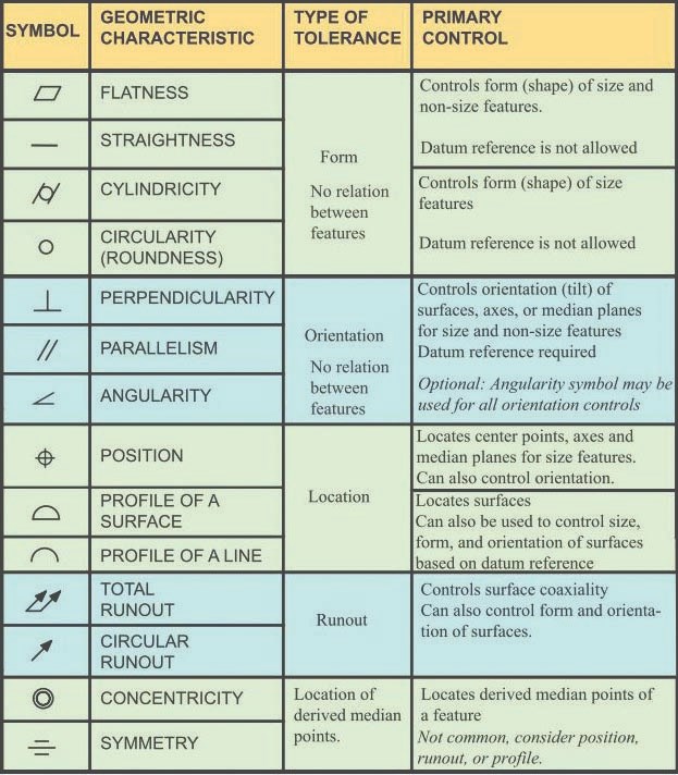
Figure 2: Guidelines for geometric dimensioning and tolerancing (GD&T) are available from The American Society of Mechanical Engineers’ Y14.5-2009 standard. Photo Credit: American Society of Mechanical Engineers
The customer will usually specify the material type, such as ABS or nylon. Even if it specifies a particular manufacturer and grade of material, ask if alternate materials of the same type are permissible. Different grades of materials have different specific gravities, molecular weights, molecular-weight distributions and other physical properties, which can impart slightly different shrinkage factors and processing attributes. The same is true for the colorant. Changing the brand or grade of material or colorant could give you the extra edge needed to get the part into spec. As a precaution, ask the customer if the parts will ever be made in more than one type of material, or in more than one color. If so, a second set of cavities and cores, or a different hot- or cold-runner system may be required to hit those numbers.
To avoid any potential disagreements in the future, have the parts inspected by an impartial third party. They have the equipment and experience to measure plastic parts accurately. Their cost and lead time are often better than what you can achieve in-house. Also request that the 2D drawing is revised after the final sampling, so as to change any “out-of-spec” non-critical dimensions to the new nominal value.
It’s incumbent on both the toolmaker and the molder to know exactly what the customer’s requirements and expectations are and how the part is going to be used before quoting a job. A drawing that looks like a “no-brainer” could end up being a “no-quote” after all the pertinent questions are asked and answered.
The Shrinkage Factor
I’ll address the big elephant in the room: Who specifies and is accountable for the shrinkage factor?
The shrinkage factor is one of the most important numbers to hit. It can cause lost profits, high scrap rates and heated discussions between the customer, the toolmaker and the molder. In my 40 years in the injection molding business, I have not experienced a single occasion in which the customer has specified the shrinkage factor—unless the customer was also a molder.
Material suppliers can’t be held accountable for specifying the shrinkage factor. There are too many variables over which they have no control. In addition to the part thickness, flow length and gate size, processing parameters such as melt temperature, mold temperature, fill time, hold time, hold pressure, cooling time (actually cooling rate) and back pressure all have an effect on how much a part will shrink. The supplier has technical data sheets, which aren’t all that technical. They typically give a shrinkage range, not a specific value, such as: “Molding Shrinkage: 0.004-0.006 inch/inch as per ASTM D955.” Those values are based on the shrinkage of a 5 × 1⁄2 × 1/8-inch test bar, edge gated on the end. Unless you’re molding 1/8-inch-thick test bars gated on the end, the shrinkage range specified by the material supplier can only be used as a reference.
The shrinkage factor is one of the most important numbers to hit. It can cause lost profits, high scrap rates and heated discussions between the customer, the toolmaker and the molder.
The toolmaker doesn’t have much control over the molding parameters, either. That’s why most toolmakers ask the molder to specify the shrinkage factor. An experienced molder deals with a lot more molds and materials then a toolmaker does, and will have a better prediction of the results. The molder can also suggest the gate location or the use of multiple gates, particularly if the part is large or made of a glass-filled material.
If the molder has a tool with similar part design, sample it in the material for the new job. It’s a quick and inexpensive way to estimate shrinkage values. Take several measurements in both directions and at various depths. The formulas for determining the shrinkage values are:
- Shrinkage Factor = 1 – (Steel Dimension/Part Dimension).
- Shrinkage Percentage = 1 – (Steel Dimension/Part Dimension) × 100
Working backwards, the correct way to calculate the size to make a mold cavity is: Part Size / (1 – Shrinkage Factor). For example, the cavity for a 10-inch-long part with a shrinkage factor of 0.005 should be: 10 / (1–0.005) = 10.050 inches. Most moldmakers do not use this equation. They simply multiple the part size by the shrinkage factor. That is incorrect. If you don’t believe me, assume the part is 40 inches long and the material has a shrinkage factor of 0.018. Run the numbers using both equations and you will see the difference. One will result in the cavity being 40.720 inches long. The other, more correct way will result in the cavity being 40.733 inches long. Yes, the difference is a small percentage, but there is still a difference. What’s interesting is that even the ASTM D955 standard uses the incorrect equation.
The second-largest attribute affecting material shrinkage is wall thickness. Ask the material supplier if he has a graph showing wall thickness versus shrinkage factor. You might get lucky. Many suppliers have graphs showing wall thickness versus flow length or cycle time, but only a few will have one for shrinkage. Uneven walls have uneven shrinkage, which is one of the primary reasons for sink marks and warpage. Coring out a part to obtain a uniform wall thickness is essential to hitting the numbers and avoiding a host of other problems.
The largest attribute that effects shrinkage is obviously the material itself. Amorphous materials, such as PS, ABS, PC and PVC, shrink a relatively small amount and for the most part, shrink isotropically (uniformly in all directions). If, for example, the specified shrinkage factor range was 0.004-to-0.006 and the wall thickness of the part was between 0.060 and 0.120 inch and uniform, a molder might suggest using a factor of 0.004 for the thinner part, or 0.006 for the thicker part, and he’s probably going to be pretty accurate. If he’s a little off, it’s probably because he didn’t account for cavity pressure. Parts will shrink less in thin and well-packed areas, such as near the gate. They will shrink more in thicker and under-packed areas, such as at the end of fill.
If the material is semi-crystalline, such as PP, PE, PBT, POM (acetal) or PPS, the shrinkage factor needs serious consideration. Crystalline materials shrink much more than amorphous materials and they shrink anisotropically—more parallel to the direction of flow and less perpendicular to the direction of flow. The shrinkage factor now becomes shrinkage factors. Using the average of the two values will probably make the part out of spec in both directions.
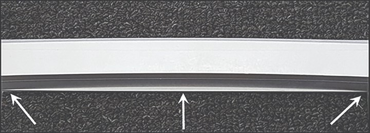
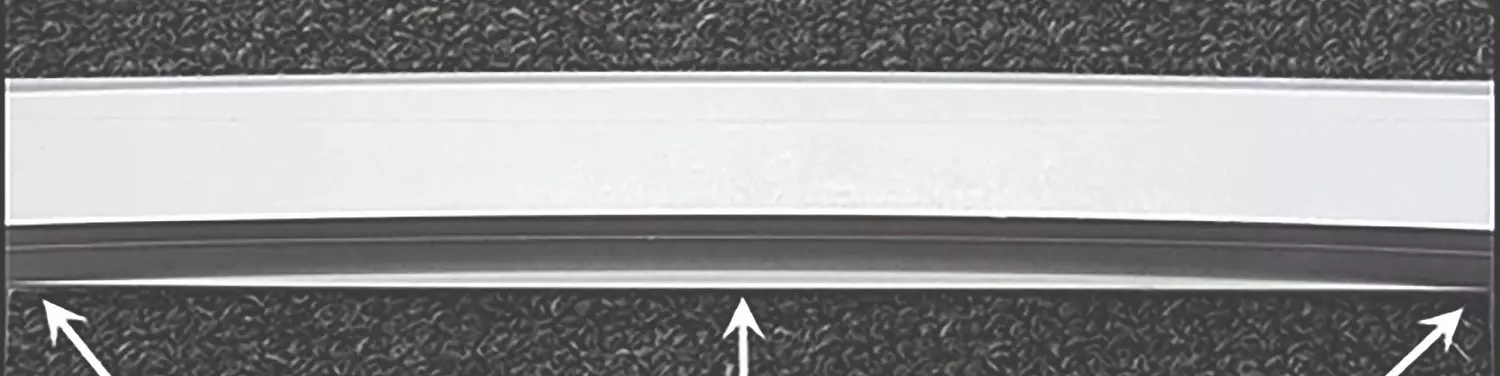
This part bowed outward so much, a convex “windage” rib was machined into the mold by the amount of the bow. The rib straightened out after the part was ejected and cooled. Photo Credit: Injection Mold Consulting LLC
Understanding the characteristics of the molding material is paramount to hitting the numbers. For example, if the material is PEEK or PPS, depending on the wall thickness, mold temperature and cooling rate, these materials can be either amorphous or semi-crystalline, which will affect the mechanical properties, chemical resistance and dimensional stability.
If the material is glass or fiber filled, the anisotropic shrinkage will be less than unfilled materials, but the difference between the two directions is considerably greater and the directions are reversed—much less in the direction of flow and much more perpendicular to flow. This is when the job often gets scary and the odds of molding a perfectly flat or concentric part are almost impossible.
On rare occasions, the toolmaker may adjust the steel after the first sampling to compensate for shrinkage-induced warp. This warp compensation is humorously referred to as “windage,” but on occasion can actually work.
Hitting the Numbers
If you are concerned about hitting the numbers, it is suggested having a flow analysis performed. Flow-analysis software programs have greatly improved over the years. Predictions of the fill pattern and gas-trap and weld-line locations are usually very reliable. While the shrinkage and warpage modules of the software may not be perfect, if done right they can give a good indication of what the outcome will be. The best results are obtained when the rheological data used in the simulation is exactly the same as for the grade of material being molded. If you’re a captive molder specializing in a particular type of product such as electrical connectors, and you frequently use a specific grade of material, ask the material supplier to pay for his material to be tested specifically for flow simulations. This can cost a few thousand dollars, but material suppliers often agree to do it since it can be used for all of their customers. Be proactive, because this testing can take up to two months to perform.
To avoid the possibility of “garbage in–garbage out” results, the molder should specify the process parameters, such as fill time, melt temperature, mold temperature, etc. The molder and toolmaker should review and discuss the results of the simulation together. You may decide a different gate location, a second gate, a thicker wall, a flow leader, or some stiffening ribs would help hit the numbers and reduce the differential shrinkage and resulting warpage.
The molder and toolmaker should review and discuss the results of the simulation together.
Prototype or “pre-launch” molds are excellent at honing in on the bi-directional shrinkage factors. They are also great at validating the cooling efficiency, vent locations, gate size and cycle time. If the production mold has numerous cavities and is expected to produce millions of parts, many companies actually require a prototype tool be made to verify their return on investment. The prototype and production molds can be made somewhat concurrently, so as not to drastically increase the lead time.
Another alternative is to make one of the cavities in a multi-cavity mold out of a “soft” or non-heat-treated steel. This would be a prototype cavity. After determining the ideal sizes on the prototype cavity, the roughed-out production cavities can then be completed.
Prototype parts can also be used for testing and marketing purposes before the expensive production mold is completed. Hopefully, the customer will agree with one of these approaches, because they offer an excellent probability of hitting the numbers, and the toolmaker picks up another mold or cavity set to build. The elimination of a stressful situation is also a welcome bonus.
Minimizing Risk
So what happens when the steel dimensions are correct based on the prescribed shrinkage factor but the parts are still out of spec? Despite what you might read in some textbooks, blogs or internet searches, there is no hard-and-fast rule. My experience has been that it depends on a combination of three factors:
1) Who hired the toolmaker?
2) What is their business relationship?
3) What is the cost of any additional changes?
The answer to question three is the most influential. A toolmaker’s not going to argue about a few dollars, but if the cost is significant, the other two factors come into play.
If the molder hired the toolmaker, he usually pays for any dimensional changes—especially if he prescribed the shrinkage factor. Most molders understand the toolmaker’s position. They know it’s only fair to pay for these changes. But some molders don’t play fair. That’s when it comes down to the business relationship. The toolmaker may decide to eat the costs in the hope of future business, or he may go to the other extreme, holding the mold hostage and demanding payment in full for its release. If a dispute occurs, negotiating the amount of tweaking and/or the extra cost is often the best solution.
If a third party, such as an entrepreneur, hired the toolmaker, he seldom pays for any additional dimensional changes. In his mind, he hired the toolmaker to build a mold to produce a part according to his drawing. Failure to meet that obligation can quickly turn ugly. I have seen several brand-new cavities and core sets tossed in the garbage to avoid expensive attorney’s fees, and I have received numerous molds pulled from other tool shops by their disgruntled owners. This is why it’s so important to discuss any concerns with the customer upfront and add a line item on the quotation for the possible cost and lead time of any size adjustments after the initial sampling.
Even if the part design is fairly simple, if the tolerances are tight and the material is semi-crystalline or glass-filled, the customer should be informed of your concerns. If they’re not happy about it, offer some of the options mentioned here and remind them that everyone will have the same problem. You’re just being professional and letting them know the reality of the situation upfront. Another toolmaker or molder might surprise them with the bad news three months from now after the mold is built and sampled. Nobody wins in that scenario.
Lastly, don’t forget that parts made from some semi-crystalline materials like PE, PP or acetal will slowly continue to shrink for weeks before reaching their final size. Wait at least 24-48 hours before performing a full article inspection. Conversely, nylon parts will continue to grow and get stronger as they absorb moisture until they reach their saturation point. Nylon parts need to be “water conditioned” for a few days before taking any measurements or performing any functional testing.
Our business is full of risks. The more steps we take upfront to minimize these risks, through the joint collaboration of the concerned parties, the more competitive and profitable we will be. And those are the most important numbers to hit.
Updated and republished from Plastics Technology.
About the Author
Jim Fattori is a third-generation molder with more than 40 years of experience in engineering and project management for custom and captive molders. He is the founder of Injection Mold Consulting LLC in Pennsylvania. jim@injectionmoldconsulting.com;


Related Content
Exploring ISO 9000 - Part 16 Control of Quality Records
A Series of International Standards for Quality Management and Quality Assurance. We begin 2022 with a review of Clause 4.16 Control of Quality Records.
Read More
Making Quick and Easy Kaizen Work for Your Shop
Within each person is unlimited creative potential to improve shop operations.
Read More
Machining Center Spindles: What You Need to Know
Why and how to research spindle technology before purchasing a machining center.
Read More
Laser Welding Versus Micro Welding
The latest battle in finely detailed restoration/repair of mold materials.
Read MoreRead Next

Sharing and Solving Pain Points of Mold Builders and Buyers
With a surge in automotive and reshoring shining a light on the current pain points of mold builders and buyers, amerimold’s technical program couldn’t have come at a better time.
Read More
Use Volumetric Shrinkage Predictions to Improve Part Quality
Simulation evaluates root cause and the impact of wall thickness, gate and cooling modifications.
Read More
Reasons to Use Fiber Lasers for Mold Cleaning
Fiber lasers offer a simplicity, speed, control and portability, minimizing mold cleaning risks.
Read More