


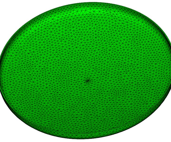
Figure 1. This lid is 12 inches in diameter and 0.06 of an inch thick. For analysis, it has been broken down into tetrahedral-shaped elements. Figures courtesy of 3D Shapes.
Question: What injection molding issue is caused by part design, mold design and process conditions, and then wreaks havoc on the parts?
Answer: Non-uniform shrinkage
If parts had completely uniform shrinkage, they wouldn’t warp, and they wouldn’t be injection molded. Non-uniform shrinkage exists in every part. The ugly ones warp, have sink or voids and the better ones meet specifications with some molded-in stress—the more uniform the shrinkage, the better the part.
Warpage is a symptom of non-uniform shrinkage, but it doesn’t tell you much about the root cause. Without analysis, you must solve these problems based on your experience and experiments at the molding machine. Wouldn’t it be better to look at the actual parameters throughout the part and the molding cycle to see how you can influence the results?


Breaking Down Shrinkage
First, some definitions. Volumetric shrinkage is the change in volume of any discrete volume of material in the part from injection through ejection. Area shrinkage is the effect of volumetric shrinkage throughout the part broken down in the x, y and z directions. Mold shrinkage is a value used to scale-up the cavity so that the part meets nominal dimensional specifications.
Every molding parameter has some effect on volumetric shrinkage. Even though a single mold shrinkage value is typically used, shrinkage is never uniform, and, surprisingly, this works as well as it does. Non-uniform shrinkage is resisted by the inherent rigidity of the part based on its features and material. A very rigid part may not warp, but will still have molded-in stress.
To make things easier to understand, consider this simple part in Figure 1 (Moldflow works just as well with the most complex part design).
Imagine if you squeeze the part around the outside and try to reduce the diameter. The middle will tend to dome upward. If the plastic shrinks more on the outside diameter, then that is precisely what happens. That volumetric shrinkage difference would be a typical result for a part packed with a single pressure until the part has reached the ejection temperature. The volumetric shrinkage would have larger values at the outside diameter and smaller values near the gate. The packing is not uniform.
Since we can measure a myriad of molding parameters, including temperature, pressure and volumetric shrinkage throughout the cycle, it is equivalent to having thousands of sensors and probes in the tool.
With simulation, the overall volume that makes up a part is broken down into smaller, tetrahedral volumes (finite element mesh) used to solve these problems. Since we can measure a myriad of molding parameters, including temperature, pressure and volumetric shrinkage throughout the cycle, it is equivalent to having thousands of sensors and probes in the tool.
Figure 2 shows the average volumetric shrinkage at ejection, which ranges from 2.4% to 11.8%. The values also change from the outside wall at each location to the center. Values are not even uniform for a single element. This is the case for all injection-molded parts. Again, it’s impressive a single mold shrinkage value works most of the time.
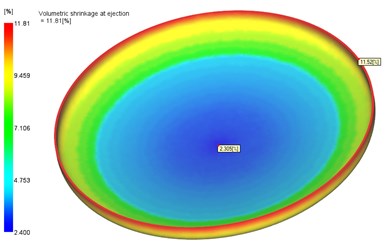
Figure 2. Average volumetric shrinkage at ejection.
Often volumetric shrinkage values with a well-designed part, tool and process have an average maximum value at ejection of around 8%. That is 8% of the volume and not the same as mold shrinkage, which is typically in the range of 0.5-2%. Volumetric shrinkage is often at least three times greater than mold shrinkage. This confuses many people when seeing values for volumetric shrinkage.
Consider a one-inch cube that is 2% smaller (mold shrinkage) in the x, y and z at ejection. It is approximately 6% smaller in volume (0.98 by 0.98 by 0.98 inches = 0.94 in3).
With mold shrinkage, you are answering the question, “On average, how much bigger do you need to build the cavity for the molded part to meet dimensional requirements?” For volumetric shrinkage, you are answering the question, “How evenly and well packed is the part?” If you do a good job attending to volumetric shrinkage and pick a reasonable average material shrinkage value, then the part will meet dimensional requirements. One depends on a little luck, and the other depends on a bit of analysis.
Simulation information will allow you to make informed, timely decisions whether you are designing a part, designing a mold, or developing a process.
The longer plastic cools until it reaches the ejection temperature, the more it shrinks. Thick areas of a part that have high values of volumetric shrinkage may result in dimensional issues and may have sink on the outside walls. With very high shrinkage, sink may effectively occur internally by forming vacuum voids. These are often mistaken for air traps that are due to melt-front advancement.
Even on a uniform-walled part such as this lid, the values will be higher far away from the gate. Gate location, gate style and sizing greatly influence shrinkage as do mold material choices and cooling layout.
Changing the packing pressure from a single value held over a set time to a varying pressure over time can significantly affect volumetric shrinkage (see Figure 3). The packing profile used accounts for how the part freezes over time. Flow simulation software can quickly determine packing profiles for uniform shrinkage.
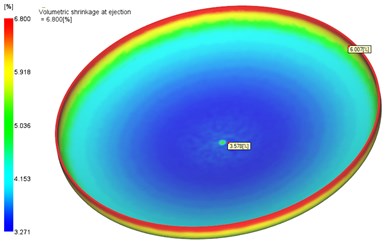
Figure 3. Volumetric shrinkage is significantly impacted when packing pressure is changed from a single value held over a set time to a varying pressure over time.
By attaining more uniform volumetric shrinkage, the part warps less and is closer to the required dimensions. These warpage results (see Figure 4) are primarily predictions of area shrinkage differences. Shrinkage values can also vary due to orientation effects from the direction of melt-front advancement (stretching polymer chains) or due to differences with fiber-filled materials. For fiber-filled materials, shrinkage in the direction of fiber orientation is often significantly less (2-10 times less) than across the direction of orientation. In this case, it is best not to use a single mold shrinkage value.
High shrinkage may severely deform a polypropylene part or live as molded-in stress with an engineering-grade material. Even with similar volumetric shrinkage, a flat plate will warp entirely differently than one with ribs or sidewalls.
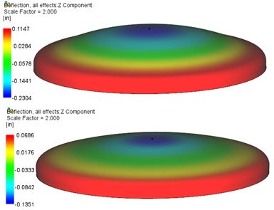
Figure 4. A part warps less and is closer to the required dimensions by attaining more uniform shrinkage.
There are so many factors affecting shrinkage that without plastics analysis, it is not possible to estimate how they all interact to affect critical dimensions. While you may see warpage, sink, voids, dimensional issues on molded parts without analysis, these are only the symptoms, and you are left to experimentation.
Analysis allows you to evaluate the root cause effects of all of these factors and the effect of modifying wall thicknesses, moving gates and improving cooling. This information will allow you to make informed, timely decisions whether you are designing a part, designing a mold or developing a process.


Related Content

Mold Design Review: The Complete Checklist
Gerardo (Jerry) Miranda III, former global tooling manager for Oakley sunglasses, reshares his complete mold design checklist, an essential part of the product time and cost-to-market process.
Read More
How to Select a Mold Temperature Controller
White paper shares how cooling channel analysis, which collects maximum pressure drop, total flow rate and heat dissipation, eases the performance evaluation of mold temperature controllers.
Read More
OEE Monitoring System Addresses Root Cause of Machine Downtime
Unique sensor and patent-pending algorithm of the Amper machine analytics system measures current draw to quickly and inexpensively inform manufacturers which machines are down and why.
Read More
Tolerancing in Mold Design, Part 2: Using GD&T to Address Conventional Tolerancing Issues
Mold designers can achieve a single interpretation of workpiece functionality when following the American Society of Mechanical Engineers Geometric Dimensioning and Tolerancing standard.
Read MoreRead Next

Use Core-Shift Analysis to Avoid Expensive Defects and Failures
The right simulation tool will show what is happening inside a cavity to reveal the root cause of problems before they occur.
Read More
How to Use Continuing Education to Remain Competitive in Moldmaking
Continued training helps moldmakers make tooling decisions and properly use the latest cutting tool to efficiently machine high-quality molds.
Read More
Reasons to Use Fiber Lasers for Mold Cleaning
Fiber lasers offer a simplicity, speed, control and portability, minimizing mold cleaning risks.
Read More