


Last month, we looked at the core issues associated with the common practice of conventional (±) tolerancing, including origins of measurement, repeatability of sizes and centers, orientation and angles and tolerance accumulation. Here, we will address these issues using the American Society of Mechanical Engineers Geometric Dimensioning and Tolerancing standard (ASME Y14.5 GD&T).
Geometric Dimensioning and Tolerancing Definitions
Before we discuss how geometric dimensioning and tolerancing (GD&T) resolves the issues associated with conventional tolerancing, let’s define datum feature identifiers, datums versus datum features, feature control frames and basic dimensions.


A datum feature identifier is a symbol that indicates a workpiece's physical features that establish the datums. Even though mold designers and moldmakers understand that axes, planes and center planes do not physically exist, they don't initially dissociate them from the cylinders, cones, individual surfaces and pairs of opposed surfaces, which are the physical elements of a workpiece that establish the virtual equivalents. These virtual elements are datums and represent the ideal (that is, perfect) equivalent to the datum features (that is, physical features) identified on the workpiece.
Datum features are imperfect; datums are perfect. This distinction is vital because any measurements from datum features include errors in the datum feature. In GD&T, measurements start from the datum — more accurately, measurements start from the datum feature simulator.
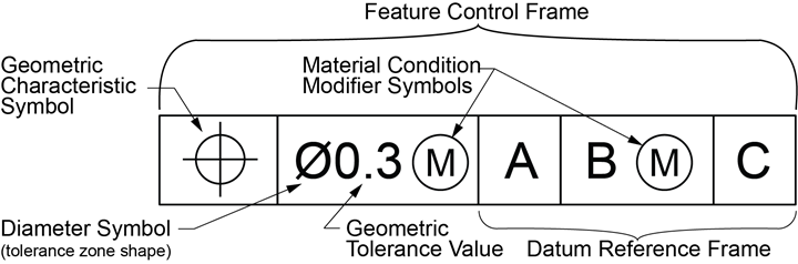
Figure 1. Feature control frame. Photo Credit, all images: Profile Services, OASIC Consulting
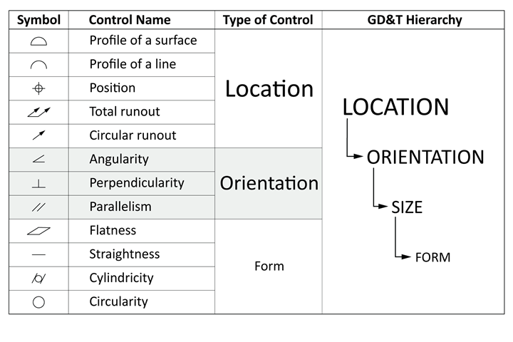
Table 1. Geometric control symbols.
Feature control frames (see Figure 1) indicate which of the four attributes (location, orientation, size and form) of a feature is being controlled (see Table 1): tolerance zone shape, tolerance zone size and the datum features that direct the workpiece setup for inspection.
Basic dimensions are theoretically perfect or ideal values to which no tolerance is applied. This is not the same as "zero" tolerance, which is a finite and impossible tolerance. Instead, geometric controls are applied directly to the feature.
The benefit of basic dimensions is that they do not accumulate tolerances. Basic + Basic = Basic. Because basic dimensions are perfect, they are not inspected. Instead, the feature is inspected per the feature control frame and the error on the geometric control is reported.
Basic dimensions may be shown either with the value enclosed in a rectangular box or without the rectangular box with a note in the title block that indicates nontoleranced dimensions are basic. The latter option precludes using conventional ± title block tolerances, but allows using a geometric control (profile of a surface) as a general tolerance unless otherwise specified.
Geometric Dimensioning and Tolerancing Steps
Next, let's review how to apply or inspect GD&T in three core steps.
Step 1: Identify datum features.
Datum feature identifiers (see Figure 2: 1a, 1b, 1c) indicate physical elements of a workpiece that establish dimension origins on engineering drawings. While datum features are imperfect physical features, the datums (or origins of measurement) they establish are perfect and theoretical. Datums are simulated by engaging near-perfect fixturing components to the datum features. The fixture components are the origins of measurement for the associated geometric controls.
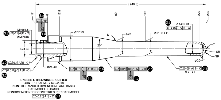
Figure 2. Sample drawing toleranced in accordance with ASME Y14.5.
Using the datum features directly as the origin of measurement would introduce any deviations in the datum feature as an error in associated measurements. Typically, datum features reflect how the component engages another workpiece. Up to three datums can be referenced in a geometric control.
Step 2: Control datum features.
Contemporary mold design is based on mating of perfect CAD-modeled components, but nothing is perfect. The designer uses geometric controls (see Figure 2: 2a, 2b, 2c) to limit how far from perfect the datum feature can deviate while still performing as required.
Step 3: Control the location of all other features with respect to the datums.
ASME GD&T establishes a hierarchy of feature attributes (location, orientation, size and form) in order of importance (see Table 1). Features fall into two categories: surfaces and features of size. Surfaces can only be located with the profile of a surface control. Depending on the functional intent for a feature of size, you can locate it with the position, runout or profile of a surface.
In Figure 2, the nontoleranced dimensions are basic and a general profile of a surface tolerance (3.1) is provided for all surfaces not directly controlled. Profile of a surface controls (3.2) are applied to specific areas to override the general profile tolerance. Position controls (3.3) have been applied to all features of size.
Geometric Dimensioning and Tolerancing and Conventional Tolerancing
Now that we understand the basic terminology and symbology of ASME Y14.5 GD&T, let's look at five ways GD&T addresses the core issues of conventional tolerancing.
1. Clear Setup and Origins of Measurement
GD&T uses datum feature identifiers to show which features to use for inspection setup. The datum reference frame of each feature control frame indicates the sequence in which to engage the datum features to set up a workpiece for inspection.
Typically, this reflects how the part mates within an assembly. Datum precedence refers to the sequence in which datums are referenced in a feature control frame. Alphabetical order has no relevance to datum precedence. However, a common practice for machined workpieces is to designate the primary datum feature as datum feature A, the secondary as datum feature B and the tertiary as datum feature C.
The feature control frame on the pattern of four 9-millimeter counter-bored holes (see Figure 3a) indicates a datum precedence of A|B|C, which means you first engage datum feature A on its datum feature simulator. Then you engage datum feature B, followed by datum feature C. For the illustrated datum feature simulator (see Figure 3b), the keys to simulate datum features B and C must be movable to engage their respective datum features in sequence.
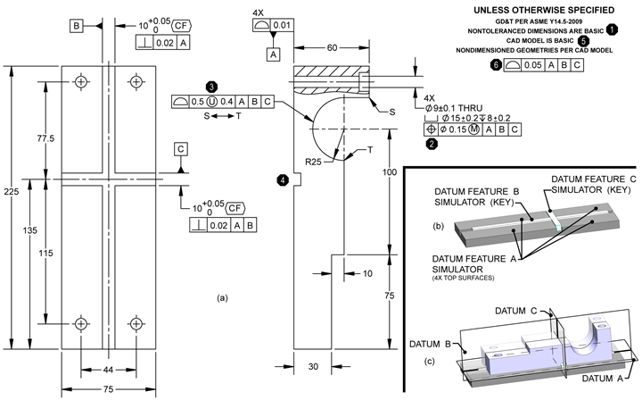
Figure 3. Datums as origins of measurement.
The resulting three mutually perpendicular datum planes are the origins of measurement (see Figure 3c) for the specified datum reference frame. Because datum features are imperfect and datum planes do not physically exist, we measure the location and orientation of controlled features from the datum feature simulators (Figure 3c). These simulators are adequately precise not to introduce errors into the measurements and to establish the origins of measurement for inspection repeatably.
2. Geometric Controls Apply to Features, not to Dimensions
Conventional dimensioning and tolerancing ties each feature to a preceding feature in a chain of tolerances and irrelevant relationships. Beyond unwanted tolerance accumulation, the more significant concern is not establishing a relationship for each feature directly to its intended functionality.
GD&T addresses location, orientation, size and form. Location and orientation are controlled relative to the datums, establishing a repeatable, independent relationship for each feature to the origins. GD&T drawings indicate the basic, or theoretically perfect, locations for features. Basic dimensions are typically shown in boxes. An alternative practice is to include a general statement on the drawing to indicate that all nontoleranced dimensions are basic (see Figure 3a, 1).
In a model-based definition (MBD) environment, where manufacturing and metrology work directly from the CAD model, it is common practice to omit basic dimensions for some features (see Figure 3a, 4) and instead indicate that the CAD model is basic (see Figure 3a, 5) and direct the user to the CAD model for further information.
Once the location of a surface or feature of size is established with basic dimensions, the feature is controlled with a directly-applied geometric tolerance (see Figure 3a, 3, 2 respectively) or with a general geometric control (see Figure 3a, 6).
Features of size have directly opposed points and a limit on the size. A feature with an enclosed boundary may be considered either a feature of size or a surface. Suppose you are concerned separately about the actual size of the feature. In that case, treat it as a feature of size by applying a tolerance to the size dimension and controlling its location with either a position or runout control. Otherwise, your primary concern is that the feature's geometries do not exceed prescribed inner and outer boundaries. Treat such features as surfaces, specifying the geometries with basic dimensions and controlling the geometries with profile of a surface. In practice, most features should be treated as surfaces. However, in either case, the locational geometric control must reference the datum(s).
Position (see Figure 3a, 2) can control the center (plane, axis or point), inner boundary or outer boundary of a feature of size. Many mold shops are familiar with hard gages, a specialized application of position controls. The position tolerance zone is centered on the feature's basic or ideal location. The default condition for profile of a surface establishes an equal-bilateral tolerance zone centered on the feature's nominal geometry. Including a circle-U (see Figure 3a, 3) modifier in a profile of a surface control allows the tolerance zone to be distributed either unilaterally or unequal-bilaterally from the feature's nominal geometry.
Profile of a surface is the most robust geometric control in ASME GD&T, whose primary use is to control the location of surfaces. However, the profile of a surface also controls orientation and form and can control the size of an enclosed geometry.
3. Repeatable Sizes and Centers
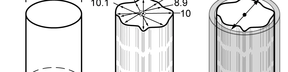
ASME Y14.5 is based on the communication of design intent and uses geometric controls to limit how far from perfect a feature can vary while still providing the expected functionality. ASME Y14.5 specifies that a feature's size and center are determined by engaging its actual mating envelope (AME), also called a true geometric counterpart.
Open setup tools, such as ring or pin gauges, machinist's vices, gage blocks, chucks and collets, are commonly used to simulate AMEs. A pin measured as ø9.8 by conventional methods acts as large as ø10.4 when inspected using the feature's AME (see Figure 4a, b, c). The AME is a precise cylinder, so measuring across any opposed points yields a repeatable size measurement. Similarly, the repeatable axis of the AME is the axis of the pin.
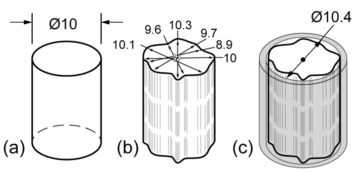
Figure 4. Conventional determination of size and center.
4. Tolerance Zones are Uniform
For surfaces, mold designers envision tolerance zones uniformly offset from the nominal geometries (see Figure 5). Whether the nominal geometry is flat, curved, complex or angled, the profile of a surface establishes a uniform tolerance zone offset from the nominal geometry. Orientation controls (angularity, perpendicularity and parallelism) establish a uniform zone offset from the nominal geometry.
For cylindrical features, position establishes a cylindrical tolerance zone centered on the basic location of the feature.
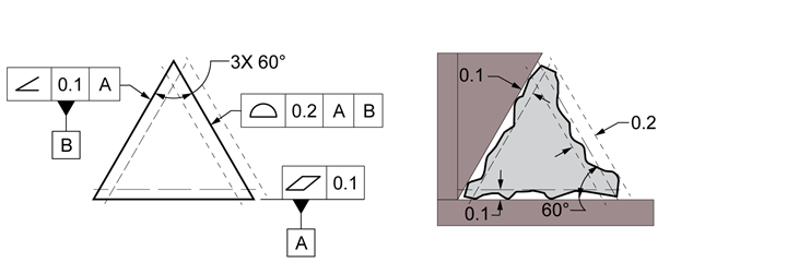
Figure 5. Uniform tolerance zones on surfaces.
5. Tolerance Accumulation is Minimized
Basic dimensions are theoretically perfect, meaning no tolerance is applied. Therefore, chaining basic dimensions does not accumulate tolerances. Instead, each feature is directly controlled for location with respect to the datums.
According to the Unless Otherwise Specified statement (see Figure 6), nontoleranced dimensions are basic, meaning theoretically perfect. The basic location of the vertical segment starting at point S is found by adding vectors one through four: 25 + 100 + 75 – 135 = 65 basic from datum C. The location of the vertical segment starting at point S is controlled by the profile of a surface tolerance applied between S and T. The total tolerance zone is 0.5 millimeter wide. The circle-U symbol indicates an unequally disposed tolerance with 0.4 millimeter of the total 0.5 millimeter tolerance zone to the side of the nominal geometry that adds mass to the part. The tolerance zone on the indicated segment is illustrated.
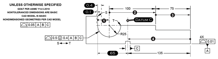
Figure 6. GD&T tolerance accumulation.
A Single Interpretation
GD&T is a language that effectively communicates design intent only when the creator and user of the engineering drawing interpret the GD&T in the same way. ASME Y14.5 provides the definitions, interpretations and rules of application of the 12 geometric controls. When the standard is followed, the result is a single interpretation of workpiece functionality.


Related Content

Mold Innovations Power Unique Auto Lighting Elements on Hummer EVs
Diamond machining, electroforming of micro-optical inserts and modified latch-lock system help injection molds produce unique forward lighting elements.
Read More
CAM Automation Increases Mold Production, Quality
Mold builder switches CAM software package after 20 years to take advantage of innovative programming strategies that reduce mold machining programming and processing times.
Read More
It Starts With the Part: A Plastic Part Checklist Ensures Good Mold Design
All successful mold build projects start with examining the part to be molded to ensure it is moldable and will meet the customers' production objectives.
Read More
Tolerancing in Mold Design, Part 1: Understanding the Issues of Conventional Bilateral Tolerancing
Mold designers must understand the location, orientation and form limitations of conventional tolerancing before changing to another dimensioning system.
Read MoreRead Next

Tolerancing in Mold Design, Part 1: Understanding the Issues of Conventional Bilateral Tolerancing
Mold designers must understand the location, orientation and form limitations of conventional tolerancing before changing to another dimensioning system.
Read More
It Starts With the Part: A Plastic Part Checklist Ensures Good Mold Design
All successful mold build projects start with examining the part to be molded to ensure it is moldable and will meet the customers' production objectives.
Read More
How to Use Continuing Education to Remain Competitive in Moldmaking
Continued training helps moldmakers make tooling decisions and properly use the latest cutting tool to efficiently machine high-quality molds.
Read More