
Machining Techniques: Are You Finished Yet?
Have you ever heard that question? People who work in the mold and die industry have probably heard it more frequently than they would like to; however, great strides in cutting tool and machining techniques in the last couple of decades are enabling more “Yes” answers.
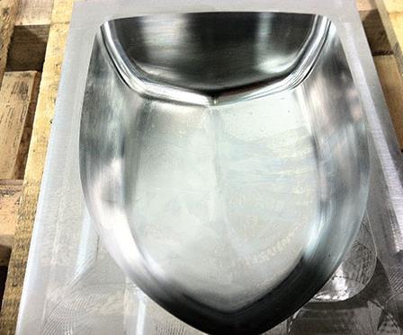
Figure 1 Truck mirror cavity. P-20 Material 30 HRC; Block Size 8.75” X 11.25” X 4”.
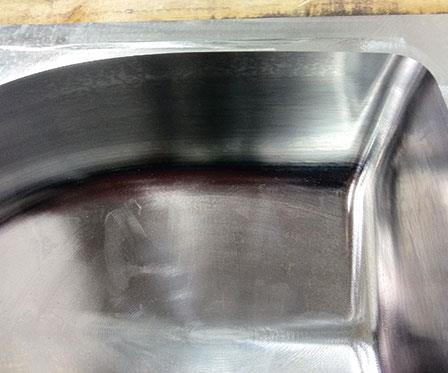
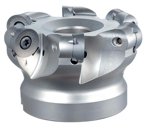
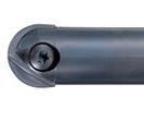
Figure 2 Button insert end mills and facemills for contour milling applications. This radius cutter features wide chip pockets for improved chip evacuation. Its specially engineered body relief shape further supporting efficient side milling, slotting, contouring and 3-D profiling.
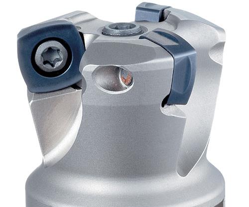
Figure 3 High-feed end mills and facemills for maximum metal removal rates in a variety of milling applications. This high-feed cutter is ideal for rough milling and large volume metal removal operations. The strong insert utilizes a chipbreaker shape that enhances cutting performance in face milling, side milling, slotting, contouring and profiling operations, while ensuring cutter rigidity.

Figure 4High precision indexable finish ball nose end mills for superior surface finish and tool life. This finishing ball end mill provides high precision and long tool life in profiling operations. The insert’s carbide substrate provides a superior balance of wear resistance and anti-chipping properties, while the spiral edge form and unique coatings enable this tool to finish mill at high speeds in a wide range of work materials.


Finishing and Roughing Strategies
Recent technologies—such as new CAM programming techniques, application-specific cutting tools, customized material substrates, special geometry for improved chip control and vibration dampening qualities, new coating technologies, etc.—have revolutionized the way we work and think in this ever-changing industry.
In the following example of a truck mirror cavity (Figure 1), we will examine the differences between a high-feed cutter and a button-style cutter. We will use a ¾-inch diameter insert ball mill for semi finishing and finishing.
Rigidity
First, we must consider how one might process a truck mirror cavity mold. The rigidity of the machining center is a key element to the milling process. For this particular example we will presume that we have a rigid machine tool. If the machine tool is not very rigid, a smaller diameter, high-feed style cutter (around one-inch in diameter) is recommended.
Tooling Choice
In the past, shops would probably choose a button-style cutter in the range of 2-inch diameter or smaller as shown in Figure 2. Although button-style cutters are still commonly used today, there are many other alternative options, such a high-feed style cutter as shown in Figure 3.


Why should we consider this new tooling? Well, for one thing, the cubic inch removal rate for the high-feed type tooling is considerably higher than the button-style cutter.
Roughing: High-Feed Indexable
In this particular truck mirror cavity example, we will be using a high-feed indexable 2-inch diameter, 4-fluted, 4-sided, 12-mm inserts in P-20 material. With this particular indexable cutter, we are able to rough at 1,130 rpm, .04” depth-of-cut, .07” chip per tooth and a feedrate of 316 ipm. That is a metal removal rate of 25 cubic inch per minute (CIPM) with a 2-inch step-over.
Having a tool that gives users the ability to remove metal at such aggressive rates is exactly what will help shops fight the labor cost many struggle with in order to be competitive in today’s global economy.
Some other benefits of this type of cutter are associated with the small depths-of-cut. The heat from cutting is released with the chips, keeping the part cooler. Moreover, if the insert happens to fail, it is less likely to damage the cutter body. The high-feed tooling is designed for applications with long length-to-diameter ratios (LDR). This style of tooling actually reduces the radial forces and increases axial forces, which are overall beneficial especially in applications that involve long LDRs. The predictability of the cutting tools and machining techniques provides users a better handle on cycle times and the ability to schedule work flow.
Roughing: Button Cutter
As mentioned previously, another option for roughing is with the button cutter. Let’s examine a 2-inch diameter, 5-flute button cutter. With this tool, we are able to run at 1,190 rpm, .05” depth-of-cut at .0125” per tooth, with a feedrate of 74 ipm—which is equivalent to approximately 7.4 CIPM.
After the comparison in performance, the superior cubic inch removal rate of the high-feed type tooling becomes obvious—25 CIPM vs. 7.4 CIPM. Based on these numbers, it doesn’t take long to decide which tool to employ. If the work cavity or core has a lot of holes for ejector/core pins, they should be drilled after roughing out the cavity when possible to minimize excessive corner chipping to inserts. So ideally, we would rough to within .035 inch of finish with the high-feed mill.
Semi Finishing
For semi finishing, we will run a ¾-inch finishing ball end mill as show in Figure 4. The process is a “Z” level semi finish pass at 6,000 rpm, .024” IPR, which is 144 ipm with a .03” step down. We can semi finish the complete cavity to within .015 inch of finish. This will eliminate any leftover material from the high-feed roughing mill. Semi finishing will cover the entire cavity, including corner radius to within .015 inch, so there will be consistent stock left for finishing.
A finish tool smaller than the corners in the final part geometry is recommended to prevent dwelling of the corners with the finish tool. Always speak with your customers and design engineers to help them understand what a difference a larger radius in the part makes in the machining process. In our example the minimum corner radius is .5 inch radius. Hence, we will use a finish tool with a 3/8-inch radius.
Finishing
The features available from your CAM software will likely determine your finish milling approach. Almost all CAM programs are capable of doing a “Z” level finish for the sides of the part, which we will employ in this example, with the same ¾-inch finishing ball end mill at 10,000 rpm, .02” IPR at 200 ipm. We will take a step down of .0075 inch for finishing, which will provide us a great finish.
Some of the CAM software packages will do a Material Out Raster Cut to finish the surfaces on the bottom. You may have to do a straight raster cut on the bottom to finish. Everything is relative to your software’s capability.
Summary
With the parameters and tooling used in this example, you can easily rough, semi finish and finish the inside of a similar truck mirror cavity in half a day. So the next time your boss asks, “Are you finished yet?” you can proudly say, “Got ‘em done!”


Related Content

Hands-on Workshop Teaches Mold Maintenance Process
Intensive workshop teaches the process of mold maintenance to help put an end to the firefighting culture of many toolrooms.
Read More
Plastic Prototypes Using Silicone Rubber Molds
How-to, step-by-step instructions that take you from making the master pattern to making the mold and casting the plastic parts.
Read More
Considerations for Mold Base Material Selection
Choosing the right material can greatly affect the profitability and cost of your application.
Read More
Advantages and Disadvantages of Copper and Graphite Electrodes
Both copper and graphite provide approximately the same end result, so it is important for a shop to consider the advantages and disadvantages of each material in order to discover what would work best in their shop floor environment.
Read MoreRead Next

Minimal Investment In New Tooling Tech Increases Productivity, Tool Life and the Bottom Line
Having a fundamental base of the facts makes it easier to detail how some of the latest innovations in cutting tool substrates, geometries and coatings can make it easier for one’s moldmaking process to go from fast to furious.
Read More
Reasons to Use Fiber Lasers for Mold Cleaning
Fiber lasers offer a simplicity, speed, control and portability, minimizing mold cleaning risks.
Read More
Are You a Moldmaker Considering 3D Printing? Consider the 3D Printing Workshop at NPE2024
Presentations will cover 3D printing for mold tooling, material innovation, product development, bridge production and full-scale, high-volume additive manufacturing.
Read More