How to Correctly Diagnose Hot Runner Electrical Issues
Watch to learn how misdiagnosing temperature control issues caused by defective or incorrectly wired components can make finding root cause and solving the problem difficult and time consuming.
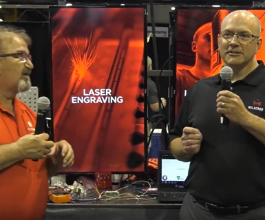
The temperature of hot runner systems is controlled by a series of heaters and thermocouples that are designed to work in conjunction with the temperature controller to keep the system at the desired temperature. In this video from last year’s Amerimold, Greg Osborn, chair elect for SPE—Mold Technologies Division, discusses how misdiagnosing temperature control issues caused by defective or incorrectly wired components can make finding root cause and solving the problem difficult and time consuming with Alliance Specialities’ Hot Runner Maintenance Superintendent Jerry Janczk.
Osborn: We're going to be talking about misdiagnosed electrical issues with your hot runner systems. A few months ago, Jerry and I talked about some of the issues that we see with hot runners systems, and a lot of people automatically think they have a poor heater in their hot runner system when things aren't working correctly. So, we talked about the things that can be a common problem and thermal couples seem to keep coming up in our conversation. So, the majority of our talk will be on thermal couple. Jerry, do you want to explain our thermal couple works?
Janczk: The thermal couples sense the heat from the end. Most systems in the United States run on a grounded system. So, it's the end of the thermal couple that actually projects all the heat and brings it back to the controller, telling the controller to put more heat out or retired heat. The problem with a thermal couple is it is so small, and it is so thin that any little pinch in the thermal couple can cause it to misread.
Osborn: Another thing people think is they can actually check the resistance of thermal couples in the system. And they should all measure the same. And that is not the case, is it?
Janczk: No, it isn't. Different lengths and different wires will give you different resistance as they go through. These two thermal couples are exactly the same. And they will tell the controller the same thing from the very end up here. But the length of it, if you took a meter and metered, it would give you a different resistance for the whole thermal couple. And people think that because the one is shorter it doesn't have the resistance of the other one, so it's no good.
Osborn: That's a good point. The other thing we talked about is the different types of thermal couples that are sold here in the US. Being a global market, we can get thermal couples from around the world, and they all have different readings. Typically in North America, we see the international standard, which is black and white. We also see the U.S. standard, which is red and white. Jerry, do you want to tell us how we can tell the difference between a positive and negative wire?
Janczk: The difference on the wiring is one is ferrous for its magnetized; that's your positive, no matter what color it is. That's your positive leg. The other one is just a general neutral, I would call it, that would go down through and the neutral hooks up to the other post. That is your main way of going over and telling the difference between thermal couples.
Osborn: The other issue we saw with thermo couples was the way that they're assembled, the assembly of the thermo couple is very important, it's a thermal couple isn’t hitting the bottom of the steel, it's not measuring the correct temperature. Jerry, do you want to explain that a little bit further?
Janczk: The end point on the thermal couple is where it reads from. If your hole is deeper, and it doesn't go all the way down, you're reading air. The air might be a different temperature. You can be off as much as 10 to 20 degrees on your heater, just because it's not reading actual metal temperature.
Osborn: In a multi cavity system that makes a big difference if you've got 16 drops in a system. And one of those thermal couples is 10 thousandths away from the steel, it will react differently in that multi cavity system, actually causing a lot of problems. It's one of the hardest things to find because only 10 thousandths of a difference between touching and not touching can create problems when you're molding.
Another problem with thermal couples is, as Jerry mentioned, it’s the end of the thermal couple that is actually getting the temperature measurement. The problem is inside of a mold, those wires can become pinched and now we have a new temperature reading point.
Janczk: In the last couple of weeks we've gone over and done a mold that had run thousands of parts — millions of parts probably — and had never had a problem. We went over and cleaned the manifold for maintenance, gave it back to the customer, the customer put it together. And now all of a sudden one side of the tool was not running properly. They were getting shorts on it, they weren't getting the same flow rate. We ended up finding out that they pinched a wire farther back on the tool. And the whole drop wasn't heating correctly. So, by the time the manifold turned around and got the plastic from the manifold to the tip, and it dropped in temperature and started solidifying, so that wouldn't turn around and flow as evenly as the other side did. It became a big issue, we ended up cleaning it again and checking it again, just to find out it was a thermal couple problem.
Osborn: We actually have an example that Jerry had in house the other day when we did our presentation pre-talk. In this thermal couple of here, you can see a few different pinch points from the tip. So, in this case, we were actually reading back towards the middle of the thermal couple probe and not at the tip. One of the ways you can test that is using hot water or something of that nature. Here's a little tip for a pinch point test: you can actually put your thermal couple into a cup of boiling water or hot substance like that. If it reads instantly when you put the tip in the water, than the thermal couple is not pinched. If you keep inserting that probe in there when it hits the pinch point, that's when it will see the dramatic temperature increase.
The other problem we talked about with hot runner systems inside of the hot manifold itself is that you have a lot of different heat sinks in that manifold. So, it's not always a heater that's causing a problem, you could actually have too much contact on that hot runner system, it's actually dissipating pulling the heat away from that manifold in the steel plates.
Janczk: Usually on the back of every manifold, opposite the drop, there is a pad that goes over and keeps pressure on the system itself. That pad usually can be made out of titanium or cut correctly so that the heat isn't draw it up through it and turned around and transferred into the manifold itself, or the mold base itself, drying the heat away from there. That heatsink that's drawn away, makes the thermal couple work harder, makes the manifold work harder, makes the drop work harder. All the heaters have to work extra hard because they're actually heating areas that are not supposed to be heated.
Osborn: I think one of the biggest things that we see in this case where you've got maybe P20 steels of manifold support. And it's actually dissipating that heat away from the manifold, so the manifold is working extra hard. We get a lot of calls that the customer thinks that our heater doesn't have enough wattage or voltage. So, they think you need a bigger heater. But the problem is not the heater itself, it's actually the supports that they're using. Another point of concern is the tip contact. And sometimes the material differences can change the amount of tip contact you need.
Janczk: You're right, you can use beryllium, copper, there are other a lot of companies have gotten into carbide tips. So different tips will draw off or dissipate heat faster than others. So, you have to be careful with the tip type.
Osborn: And another thing is the plastic material itself, right? So let's say they built a manifold and it was specked out far probably propylene material that would require more of a tip contact on the cavity block to control the gate. If they switch to a nylon material that runs at a higher temperature, they're going to have to reduce that tip contact.
Jerry and I were talking about this one as well. So, you've got a brand new manifold right in your sampling, you've got the prints for it right? Jerry doesn't have that luxury all the time, right? Because he gets 20 year old manifold systems that are in ill-repair. There are no prints for it. And he's trying to determine what is the wattage of this? What's the resistance of the heater supposed to be? Well, one of the formulas you can use is you can take the voltage squared divided by the watts and that'll give your ohms resistance. I've got a sample manifold heater here. And on most heaters the voltage and wattage is listed on there. So, in this case, here we had a 230 volt heater 960 watts, when you do the math, it turned into a 55 ohms resistance. So, we could verify this heater as good or not by just looking at the stampings on the heater and then doing the arithmetic there.
Janczk: One of the other things that we forgot to get into a little bit were the plugs. Most of the plugs, your contact wires and everything else are in a pin. Different companies use different plugs at different times. Some of them are pushed in, some of them are screwed in from the outside for connections and everything else. The biggest thing that we've seen is they'll go over and put pins together with their wire sets. They go over and push a pin back or push a pin off to the side where they're not making good contact. And it's just like plugging in a plug in an outlet. It's going to get hot. It's going to come up to a certain temperature, but then it's not going to draw all the way.
Osborn: That's correct. Another thing we didn't touch on that we should have is splicing thermal couple wires. We've talked about pinching the wire in the system itself and then adding new wire to the length of that. And a lot of people are in the misconception that you can just grab the similar gauge wire and splice your wires but you actually need to maintain those same ferrous and non-ferrous connections.
Janczk: You're almost better just trimming them back on both ends, stripping them back and using the original wire. That saves you from getting a different size gauge of wire coming back to the plug, which can affect your rating immensely.
Related Content
Fundamentals of Designing the Optimal Cooling System
The right mold components can help improve mold cooling and thereby produce higher-quality parts.
Read MoreHands-on Workshop Teaches Mold Maintenance Process
Intensive workshop teaches the process of mold maintenance to help put an end to the firefighting culture of many toolrooms.
Read MoreMachining Center Spindles: What You Need to Know
Why and how to research spindle technology before purchasing a machining center.
Read MoreHow to Eliminate Chatter
Here are techniques commonly used to combat chatter and guidelines to establish a foundation for optimizing the moldmaking process.
Read MoreRead Next
How to Use Strategic Planning Tools, Data to Manage the Human Side of Business
Q&A with Marion Wells, MMT EAB member and founder of Human Asset Management.
Read MoreReasons to Use Fiber Lasers for Mold Cleaning
Fiber lasers offer a simplicity, speed, control and portability, minimizing mold cleaning risks.
Read MoreAre You a Moldmaker Considering 3D Printing? Consider the 3D Printing Workshop at NPE2024
Presentations will cover 3D printing for mold tooling, material innovation, product development, bridge production and full-scale, high-volume additive manufacturing.
Read More




.jpg;maxWidth=300;quality=90)


.png;maxWidth=300;quality=90)


_300x250 1.png;maxWidth=300;quality=90)

