Share
From specialized cooling component materials and conformal cooling inserts to standard machining practices employing new mold components, mold cooling has evolved and increased in efficiency in recent years.
Historically, mold cooling systems were designed to circulate water or other media through the base plates, but not necessarily within the cavities. Newer technology creates optimized circulation throughout the mold plates and cavities.
Featured Content


There are three keys to establishing the most efficient mold cooling process possible and producing quality products:
- Keep the cooling system a proper distance from the parting line and the molded part.
- Make sure the cooling line diameter is large enough to overcome the convection of the plastic material temperature into the surrounding steel.
- Use turbulent flow to pick up the maximum amount of heat possible from the steel.
An important safety measure is ensuring that all supply and exit lines remain on a mold’s bottom and/or non-operator side while the mold is in the molding machine. This protects the operator and also retains any necessary electrical connections high, dry and safe in the production environment.

Figure 1. Traditional cooling components include baffles, bubblers and heat pipes. Photo credit, all images: Hasco GmbH
There are numerous products available to help you accomplish the proper cooling setup in your mold design. Traditional cooling components include baffles, bubblers, heat pipes or cooling pipes (see Figure 1), spiral cooling cores, standard O-rings, and diverter plugs. More recent advances include conformal cooling inserts, specialized O-ring-type diverters, and flexible cooling lines that are installed into a milled channel and used with a copper paste for improved heat transfer.
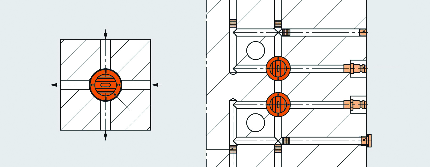
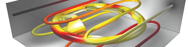
Figure 2. New technology allows the cooling lines to cross each other on the same plan.
Mold Plate Cooling Technology
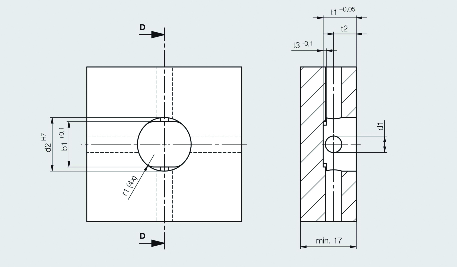
Figure 3. This diagram shows a plane and side view of a cooling technology installation.
New mold plate cooling technology also exists that allows cooling lines to cross each other on the same plane (see Figures 2 and 3). This enables the cooling lines to surround all four sides of a cavity or core, providing even temperature distribution throughout the system without the expense of additional machining. This makes it now possible to achieve cooling flow not only that completely surrounds each cavity and core, but also on a single level or plane within a mold base plate or insert. Multiple levels with thicker plates or higher die heights are not necessary.
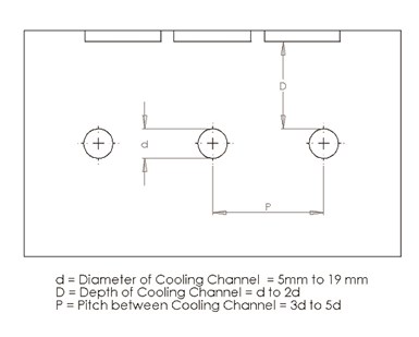
Figure 4. This image shows recommendations for cooling line size and location.
Gun-drilled mold plate cooling lines are machined on single and multiple levels to achieve the desired cooling within the mold assembly. Waterline pitch locations along the plane view should be between three and five times the cooling line diameter, with a distance of one to two times the cooling line diameter from the parting line to the first level and the same distance between each additional level (see Figures 4 and 5). This results in additional steel requirements for the plate thickness and increases overall mold height.
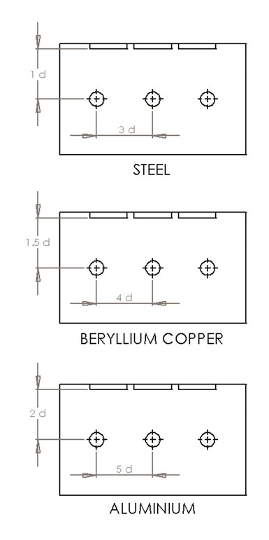
Figure 5. The cooling line pitch locations vary for different cavity/core metal materials.
Diverters can also be installed on different levels to help the cooling media move in specific directions through the mold base and cool the system properly. Mold cooling lines in the mold base plates generally are 5, 8 and 12 mm, or 5/16, 7/16 and 9/16 inch in diameter.
Another critical consideration is that the distance between the cooling lines and the mold core wall or insert split should never be less than 3.18 mm (0.125 inch). A thin wall condition between the insert split lines and the cooling lines could jeopardize the life of the mold. To overcome temperature increases and help with cooling and curing of molded products, heat must transfer from the mold steel into the cooling medium or from the molding plastic to the steel. There are two forms of heat transfer calculation: conduction, or transfer from plastic to metal material, and convection, or transfer from steel to the cooling medium. Both are calculated in British thermal units (Btu), or the amount of energy needed to cool or heat 1 pound of water by 1°F.
The formula for calculating conduction or Fourier’s Law is H = KAT(t2-t1)/L, in which:
K = metal material conductivity factor
A = area of the cavity/core in contact with the melted plastic
T = cycle time per shot
t2 = temperature of the melted plastic
t1 = temperature of the cooling medium
L = distance from the molding face to the edge of the cooling diameter hole.
The formula for calculating convection or Newton’s Law of Cooling is H = ms(t2-t1)T, in which:
m = weight of cooling medium (area of passage diameter A × velocity of cooling medium V × hours of curing time Ts × specific gravity sg)
s = specific heat value of the cooling medium
t2-t1 = temperatures at the inlet and outlet of the mold
T = time in hours that the cooling medium takes to circulate.
Traditional mold design cooling formulas are now integrated within most cooling analysis design software, which works on these same principles and calculations, along with 3D design in finite element data (see Figure 6).

Figure 6. Cooling analysis software uses 3D data in calculations.
Of course, the specific mold and molding materials being used will dictate the cooling requirements of any particular molding job. Cooling system designers must identify not only the steel that will be used for the mold plates and inserts, but also the plastic material to be processed and the part geometry. They also should investigate new mold components that can minimize plate thickness, decrease hot spots in cavities and cores, and reduce machining time and costs. This will help achieve an optimized cooling cycle time for each application.
RELATED CONTENT
-
How to Use Simulation to Achieve a High-Gloss Surface Finish
Combining simulation, conformal cooling, and a rapid heat and cooling process can predict and produce the required surface finish for high-gloss plastic parts.
-
What's So Cool About Manufacturing? Students Use a Camera to Find Out
Neu Dynamics Corp. collaborates with DVIRC, Ignite-MS STEM/Science and the Pennsbury School District to foster an interest in moldmaking and manufacturing among the younger generation through a state-wide student video contest.
-
Technology and Sourcing Guide 2023: Mold Components
Mold components make the mold work and the mechanisms used to deliver a quality end product. Key components include mold bases, pins, ejectors, lifters, bushings, guides and alignment devices.