
How to Increase the Process Speed of Die Sinking EDM
An increase in productivity of approximately 30 percent, and up to 100 percent with pre-milled molds, is possible with new EDM technology.


It is possible to increase the speed and productivity of die sinking EDM.

Die Sinking EDM
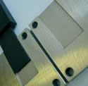
Figure 6: Lamellar electrode 40 mm depth. The challenge consists in achieving an optimum homogeneous roughness. With this lamellar electrode (20 x 1 x 40mm, taper 1 degree, undersize of 0.5mm, EDM3 graphite and only flushing by motion) without this new EDM technology the depth of 40 mm and the surface finish of VDI24 have been performed in 230 minutes; however, with this new EDM technology the machining has been achieved in 170 min., with a speed increment of 36 percent, and electrode wear of 0.3 mm. The quality of the surface is perfect.
Figure 1: Potential lies in the flushing.
Figure 4: With a dovetail lamellar electrode (15 x 1 mm) a depth of 20 mm was EDMed in 70 minutes without the new EDM technology; with the new Figure 4: With a dovetail lamellar electrode (15 x 1 mm) a depth of 20 mm was EDMed in 70 minutes without the new EDM technology; with the new EDM technology in 50 minutes, meaning an increase in speed of 40 percent with constant roughness, gap width and electrode wear (wear 0.2 mm, only movement flushing).

Figure 3: Finding the right moment to increase the current.
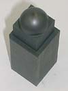
Figure 5: With a spherical electrode of 20 mm diameter, a depth of 20 mm and a final roughness of Ra = 1.6 um is EDMed. Thanks to this new EDM technology, the gain in machining speed is approximately 25 percent.
Figure 2: Removal and surface quality determine the time requirement.
Developments in the EDM process and its technology along with improvements in accuracy, automation and micro-moldmaking technology can pay enormous dividends to the domestic moldmaking industry.
Speed Is Not the Solution
Increasing drive speed is one solution to improving the speed of die sinking EDM. In this way the unproductive times for lifting movements are reduced; however, the gain in speed is limited to small electrodes and very deep cavities. In addition, above a certain speed the electrode wear is considerable, and very high axis speeds result in extreme strain on the mechanism, make the machine more expensive and shorten its working life. Therefore, it is wrong to believe that a general increase in the process speed is only to be achieved by rapid lifting movements. The contribution of fast axes to the machining process is just one supplementary aspect to a complex interaction that encompasses the generator, process control, gap width regulation and the mechanism. Die sinking EDM requires intelligent flushing.


Potential Lies in the Flushing
You can imagine the EDM process as being a balance between the EDMed and evacuated material in the gap. If this balance is not present, then either you flush the machining area unnecessarily—involving a loss of time and additional instability of the process—or you EDM the same particles several times, which cannot be removed from the gap sufficiently (see Figure 1).
Die Sinking EDM
Before the material can be evacuated from the gap you must remove it from the workpiece. So how can you achieve more removal? As in the case of all optimization problems, the greatest gain potential lies where the efficiency is smallest. The efficiency of a single discharge with a cathodic poled workpiece is theoretically about 25 percent.1 In addition there are some factors that make the efficiency even worse (e.g., process control problems, non ideal flushing conditions, small gap width), so that realistically you must reckon with an efficiency of less than 10 percent.2
Removal and Surface Quality Determine the Time Requirement
In the case of EDM, the objective is always to optimize the removal performance of the machining on one hand, and to achieve the surface quality of the workpiece to be machined on the other hand. The workpiece, when machined, is intended to display a certain final roughness and a certain form precision. In addition, two conditions are called for: (1) as small a thermally influenced area of the workpiece surface as possible, and (2) as low an electrode wear as possible. These marginal conditions determine the machining time and costs for workpiece production. In practice, a sequence of technological parameters is used because starting out from the roughing to finishing settings, the pulse energy is gradually reduced until the required technological results are achieved. Once again the law of nature applies: you can quickly achieve results of modest quality, but only slowly results in high quality (see Figure 2).
Physical Processes Show a Solution
The approach toward an ideal state means moving the characteristic curve in the direction of the arrow. That means faster EDM with the same gap width, roughness and wear. If, up to now, the discharge energy of the EDM pulses was increased, regrettably you also only had greater roughness and a greater gap width so that the gains in speed during roughing were lost again through longer finishing. You will find a way to a solution if you return to the basics of EDM theory—to the physical processes leading to the formation of the spark and metal removal.
During the discharge, you can identify three main physical phases in succession: (1) the build-up, (2) discharge and (3) fade phases. In the first phase the discharge canal is built up. After passing through the working medium, the current flows almost exclusively on the surface area of the discharge canal and the anode is partially evaporated by the electron bombardment. The electrode wear mainly takes place here. Every pulse—whether contributing intensively to removal or not— causes microscopic wear. In the discharge phase, the electrical energy supplied causes melting or evaporation of material mainly on the workpiece. The fade phase begins with the switching off of the power supply. The plasma canal collapses and the partially evaporated, partially liquid material is ejected.3
When to Interrupt Pulses
During the discharge, a crater forms in the workpiece. Fundamental studies of discharges have shown that the growth of the crater in the workpiece stagnates from a certain time.4,5 This is because a balance forms between the energy supplied and the energy lost, as well as energy that is used for the maintenance of the plasma and the heat loss to the workpiece and dielectric. This asymptote of the crater growth can be recorded in real time from the spark voltage and current.
However, why is the asymptote of the crater growth so important? Because this is the right moment to interrupt the pulse. It is unnecessary to let a pulse last longer if the target radius of the crater and the required roughness have been achieved. You can begin with the next pulse immediately. The time required by the pulse to reach this state also is not constant, as the speed with which a discharge reaches a certain spark base diameter depends on the macroscopic situation in the gap and the local geometry in the spark discharge area. With this first measure alone, you will optimize the number of discharges per unit of time and increase the removal rate.
When to Increase the Current
If you now observe the charge's fade phase you will see that the removal from the workpiece is caused by the collapse of the plasma canal. The sudden drop in pressure—triggered by switching off the power—causes the evaporation and ejection of superheated material.2 The plasma canal has a very high temperature and pressure. The gradient of its collapse influences material removal. The more abruptly the energy disappears, the better the crater material will be ejected. In order to enhance this effect, a special trick is employed: before the pulse is interrupted, the current is increased briefly. The idea of increasing the pulse current is not new6, the innovation is the definition of the point in time when this increase is to take place. The increase in the pulse current has no consequences for the roughness, wear or gap width, but does increase the removal (see Figure 3). In addition, as the removal per pulse is greater, you need fewer pulses for the machining, and therefore the wear sinks.
Removal Rate Doubles in Part
This new machining strategy (asymptote detection, current increase and pulse interrupt) is the subject of a patent application for its use in new EDM die sinking systems. The results are in accordance with the theoretical reflections, especially where good flushing is guaranteed (e.g., pre-machined workpieces). For these machining jobs removal rates have doubled. In the case of the applications in Figures 4, 5 and 6 the gains lie from 25 to 40 percent.
Generator Brings Striking Improvements in Performance
The innovative generator offers an increase in productivity of approximately 30 percent; however, up to 100 percent with pre-milled molds that occur increasingly nowadays through synergies with HSM. This refers to all roughing and finishing using copper and graphite electrodes. The advantages are particularly great with good flushing conditions and pre-milled workpieces. These convincing results explain that it is possible to increase the speed and productivity of die sinking EDM, and the potential for improving this technology is still considerable.
References
- Karden, A., Funkenerosive Senkbearbeitung mit leistungssteigernden Elektrodenwerkstoffen und Arbeitsmedien, Shaker Verlag, ISBN 3-8265-8392-2 (2001).
- van Dijk, F., Physico-mathematical analysis of the electrodischarge machining process, Katholieke Universiteit te Leuven, Proefwerk (1973).
- König ,W.-Klocke, F., Fertigungsverfahren, Abtragen und Generieren, Springer Verlag, ISBN 3- 540- 63201-8 (1997).
- Dibitonto,D.D et alii, Theoretical Models of the Electrical Discharge Machining Process - II. The Anode Erosion Model. In: J.Appl. Phys. Vol. 66, No 9 (1989).
- Eubank, P.T, et alii, Theoretical Models of the Electrical Discharge Machining Process - III. The variable Mass, Cylindrical Plasma Model. In: J.Appl. Phys. Vol. 73, No 11 (1993).
- Otto, M., Korenblum, M.V., High frequency transistor generators for EDM, ISEM 5, Wolfsberg (1977).


Related Content

Maintaining a Wire EDM Machine
To achieve the ultimate capability and level of productivity from your wire EDM on a consistent, repeatable and reliable basis, regular maintenance is a required task.
Read More
Fundamentals of Designing the Optimal Cooling System
The right mold components can help improve mold cooling and thereby produce higher-quality parts.
Read More
Considerations for Mold Base Material Selection
Choosing the right material can greatly affect the profitability and cost of your application.
Read More
Forces and Calculations Are Key to Sizing Core Pull Hydraulic Cylinders
To select the correct cylinder, consider both set and pull stroke positions and then calculate forces.
Read MoreRead Next

How to Implement Ultra Productive EDM
Steps to help maximize the potential of your current die sink or wire EDM system.
Read More
Are You a Moldmaker Considering 3D Printing? Consider the 3D Printing Workshop at NPE2024
Presentations will cover 3D printing for mold tooling, material innovation, product development, bridge production and full-scale, high-volume additive manufacturing.
Read More
Reasons to Use Fiber Lasers for Mold Cleaning
Fiber lasers offer a simplicity, speed, control and portability, minimizing mold cleaning risks.
Read More