
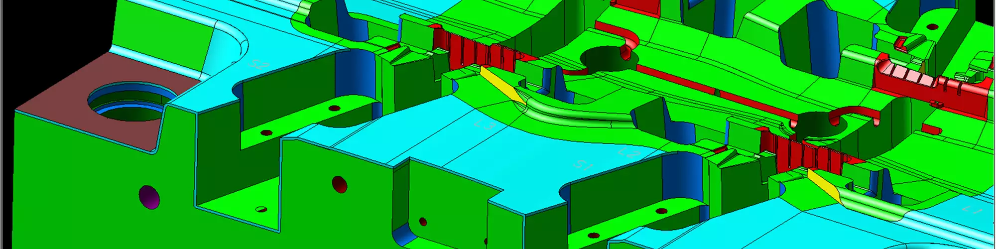


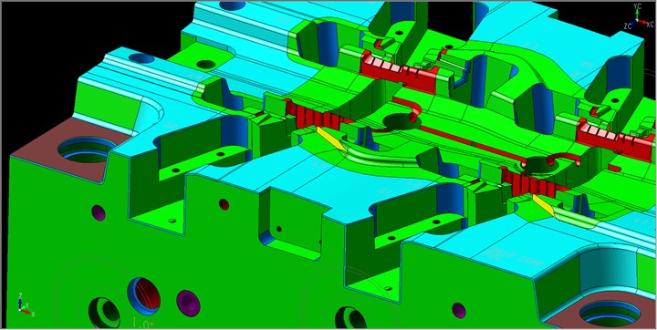
The face colors on this core block help to communicate the purpose of different areas of the block to the shop (part, seal off, clearance). Photo Credit: Superior Tool and Mold
Traditionally drawings have been an indispensable and unambiguous definition of the finished product—a vital part of the service agreement between the customer and those responsible for tooling and inspection. Unfortunately, for many shops, 3D models are still only a supplement to the official authority of the drawing. However, a growing number of companies involved in product design, mold design, machining and inspection are finding ways to effectively communicate across these functions using model-based definition (MBD)—without any drawings.
A primary benefit of MBD is faster turnaround time. This is important, as a project begins with the customer submitting their part design to the molder as a 3D CAD model—including nominal sizes and locations of the geometry—that are accurate to five or six decimal places. This model serves as the basic, unambiguous definition of size and form with no required dimensions.


Using MBD, the customer can code tolerances, surface finishes and special features onto the faces of the model using color attributes. The model file can also include a table defining each color, as this often varies from shop to shop. These face colors on the product model are then carried directly into the mold design and CAM software to automate cycle parameters, eliminating the need for workers to re-enter critical information from the drawing manually.
Turnaround speed can be increased further by limiting this MBD strategy to classes of parts that support the fastest NC machining and process capabilities. For example, smaller parts without any extra-tight design tolerances and moldable in standard aluminum mold bases.
MBD and STEP
STEP (Standard for the Exchange of Product Data) is a standard 3D CAD file format controlled by the International Organization for Standardization. It is a popular neutral 3D CAD file format that is interoperable among various CAD programs. Over the last five years, CAD vendors have been implementing a new STEP application protocol (AP) that builds on top of the popular STEP AP 203 and 214 formats. Basically, the color-based MBD process used in moldmaking today is supported by the AP 214 and AP 203 edition two formats, and the new STEP AP 242 adds the ability to connect tolerance information directly to the model.
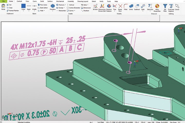
Shown here is a STEP AP242-based position tolerance definition attached to a set of faces in a part model. This machine-readable definition of thread requirements can be read directly by process planning and inspection software. Photo Credit: Kubotek3D
AP 242 for managed model-based 3D engineering defines critical manufacturing annotations, including geometric dimensioning and tolerancing (GD&T) and their relationship to the faces of the 3D model. These annotations and the nominal size and position of the precise geometric model provide an unambiguous part definition. This form of MBD provides process efficiency by eliminating the need to translate the design into detailed drawings and better support automation of downstream activities such as NC machining and inspection.
STEP AP 242 adds “machine-readable representation of manufacturing and assembly information, such as assembly tolerances, surface finish and manufacturing process information.”
The extended definitions in STEP AP 242 can improve the MBD process by providing a model that includes standard tolerance, surface finish and unique feature definitions that can be used instead of face color attributes. All of this means that the part information the molder needs to automate CAD, CAM and CMM processes can be in one MBD file directly from the customer. This eliminates potential errors in mapping non-standard face colors from the customer model to their specific processes.
The ultimate goal of STEP AP 242 for MBD is to share specific product, manufacturing and inspection definitions across all software in the supply chain using a standard, machine-readable 3D format, eliminating reliance on technical part drawings.
The Bottom Line
Humans make mistakes. People reading critical information from drawings and re-entering it into software takes time and introduces the risk for errors at several points during the manufacturing process. The bottom line is that technical drawings are a significant source of miscommunication and add complexity to the definition process.
This change may be a slow one for many because of the widespread training needed in geometric tolerancing and significant process and cultural changes across extended teams. However, if your shop reacts early to this transition, you’ll have a competitive advantage.


Related Content

Products and Services for Multiple Moldmaking Needs
New year, new technology roundup! Featured here is a collection of product offerings, from profile milling cutters to industry-specific CAD/CAM software to innovative hot work tool steels.
Read More
How to Select a Mold Temperature Controller
White paper shares how cooling channel analysis, which collects maximum pressure drop, total flow rate and heat dissipation, eases the performance evaluation of mold temperature controllers.
Read More
How to Improve Your Current Efficiency Rate
An alternative approach to taking on more EDM-intensive work when technology and personnel investment is not an option.
Read More
OEE Monitoring System Addresses Root Cause of Machine Downtime
Unique sensor and patent-pending algorithm of the Amper machine analytics system measures current draw to quickly and inexpensively inform manufacturers which machines are down and why.
Read MoreRead Next

Reusing CAD Data
A true direct modeler can help mold builders work more easily with customer design data.
Read More
Design Modeling Package Integrates Tools to Organize Projects
Xcentric Mold & Design (Chesterfield, MI) prides itself on being a low-volume, short-run, complex custom mold specialist and a prototype mold provider with leadtimes as little as one to15 days.
Read More
3D CAD Software Release Ensures Manufacturing Agility and Efficiency
Enhanced model-based definition capabilities including improved color tools, expanded proprietary readers for STEP files and more round out Kubotek3D’s KeyCreator MfgCAD software.
Read More