
Share
Read Next


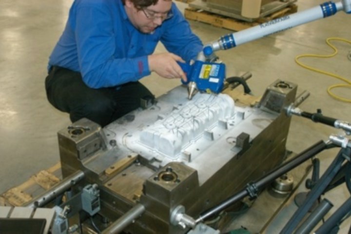
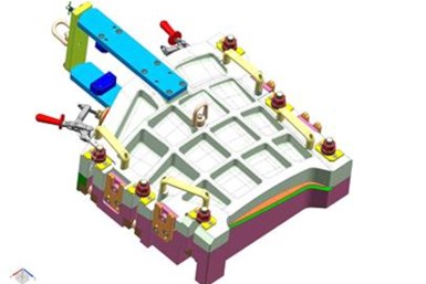
Onsite data collection of a mold for reverse engineering to understand adjustments that were made to create the part. Photo Credit: 3D Engineering Solutions
Tuning a mold takes time, so moldmakers are always open to learning about options for reducing the time this process takes. Reverse engineering is a tool-correction strategy that reduces the overall time involved with mold tuning a new tool, a damaged mold or a copy of an existing tool. But first, let's break down the challenge of each tuning scenario.
New Molds
For example, a common struggle for new molds is fully understanding and accommodating the effects of shrink. Often, a moldmaker gets the mold close, but leaves it material-safe. Then he/she slowly cuts away material until the combination of that geometry and the process parameters yield an acceptable part.


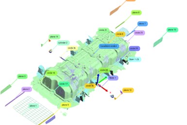
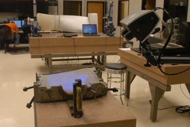
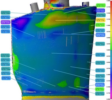
Raw point cloud data (raw points and plane data) obtained from probing and laser scanning the mold.
Each trial is an iteration that gets the mold closer but hopefully doesn't go too far. The tighter the tolerances involved and the more dimensions requiring tight tolerance, the more iterations are needed and the higher the frustration level as the mold builder balances these competing issues.
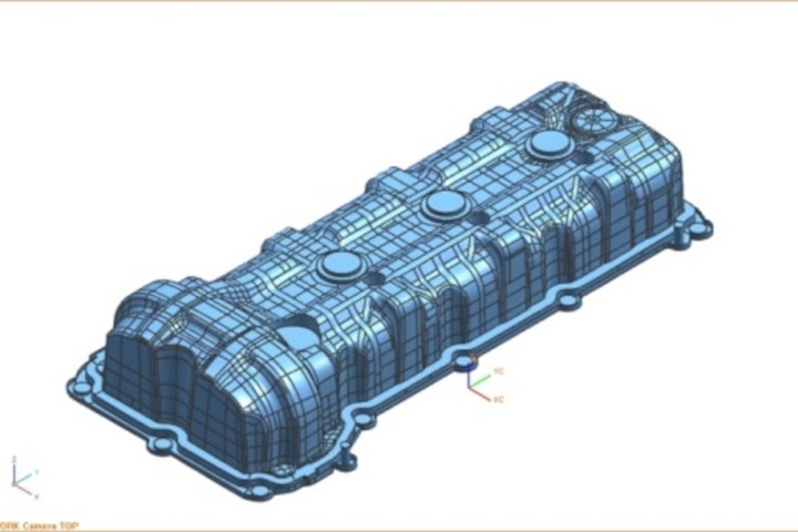
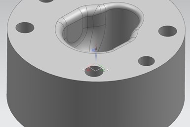
The finished hybrid CAD model created from the data of the captured tool, which combines NURBs surfacing with parametric CAD modeling.
Damaged Molds
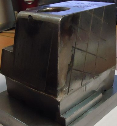
This damaged and temporarily repaired tool had no design documentation, so it was reverse engineered to create a new tool.
A part trapped in a mold will quickly damage that tool, causing cracks or broken mold components. The damage often occurs during production, so the moldmaker must quickly create and install the replacement components. The problem is that the CAD models for that component are in the nominal and un-tuned condition.
For example, when a shop first creates a mold, it may go through several iterations to tweak or tune the resulting part. As soon as that part meets the print, the shop starts production without updating the original CAD model. So, when a mold component breaks, the moldmaker must repeat the tuning process... or does he?
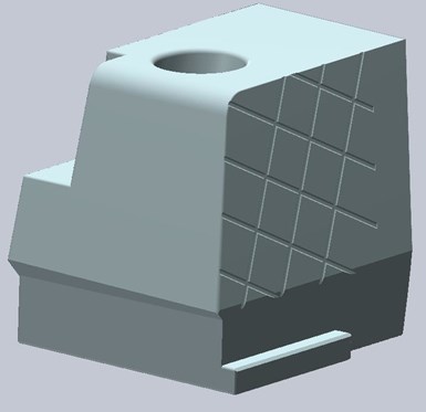
The final hybrid CAD model of the repaired stamping/forming tool includes NURBs surfaces and parametrically-created features. The majority of these surfaces match the raw data to within 0.001 inch.
Copy of Existing Molds
If a shop has a well-functioning mold that requires more cavitation or duplicate molds, the shop always prefers an exact copy. An example of a mold that produces good parts helps the mold builder reverse engineer the geometry for any copies (assuming cooling and other parameters are not altered). Capturing accurate mold data is an inexpensive insurance policy for if and when a mold breaks. The shop can also use that data to monitor wear over the mold's life.
Mold builders can reverse engineer their way out of time-intensive mold tuning.
This is a worn copy of a tool that overmolds onto an aerospace part for which reverse engineering was required because there was no existing design data for this part.
The Process
Mold builders can approach each of these cases with the same process. Here are the steps for each application.
Copy of Existing Molds
Reverse engineering is a straightforward solution for a shop that must create an exact duplicate of an existing mold. The shop can either use an RA laser scanner or a structured light scanner (blue light or white light) to scan the mold, which requires a light coating of a powder or paint to capture the mold's geometry data. The coating is usually between 0.0005-0.0020 inches thick if applied well.
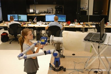
Using a laser scanner and probe to capture data on the worn tool.
A chromatic white light sensor uses the frequency (color) of the light reflected to measure distance and does not require a coating. This sensor is quite adept at scanning both specular and transparent parts. Measurement uncertainties of about 0.0035 inches for laser, between 0.0002-0.0020 inches for structured light and 0.0001 inches for CFS are possible.
Multiple actual “good” parts were scanned and averaged and then compared to the data from the worn tool. The data was then reviewed with the customer to understand what features were needed and what features were simply worn areas of the tool.
Once the scanner obtains the point cloud, it generates a very large (accurate within 0.0001 inches of the point data = tessellation tolerance) STL model. A non-uniform rational basis spline (NURBs) surface model can then be created by laying points onto the point cloud and creating surface patches that closely match the original point data. This process is highly adjustable.
For typical reverse engineering work, maintain a deviation of no greater than 0.003 inches from the original point cloud data. Note that this is the maximum deviation and that in NURBs work, this only occurs in small areas of a part. At the same time, the balance of the surfaces are well within 0.001 inches.
All of the data was then used to model new tooling. A new seal design was added as well as other features to make the tool easier to use.
If the moldmaker spends more time (usually in multiple hours), he can reduce the maximum 0.003-inch deviation to 0.001-0.002 inches and combine the NURBs model with the parametric CAD features (such as the block of material and mounting and alignment holes) to create a copy of the mold.
The duplicate model will be accurate within a measurement uncertainty of just over 0.0010 inches (adding all the sources of error mentioned above) depending on shop requirements.
Mold complexity also determines process time (between 4 to 20 hours). However, some jobs can take more than a week due to complex surfaces with extremely tight tolerances that require additional CAD modeling time.
Damaged Molds
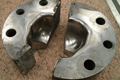
This broken stamping die had no existing design data and required a quick turn on the model to resume production.
When a mold is damaged, a shop can scan the broken area, use surrounding data to repair the damaged area digitally and then create NURBs surfaces. The moldmaker must closely watch the digital repair to determine the integrity of the data. Also, surrounding mold surfaces can be bent or mangled, indicating that the data in that area is useless. A mold builder must do the best with what he has.
The finished CAD model was created from the broken halves of the tool. A hybrid model was needed to incorporate the tuned features of the tool.
A moldmaker should scan newly tuned tools before they go into production. This is an inexpensive strategy to ensure mold quality. The raw scanning process does not take long and will preserve the “ideal” state of the newly tuned tool. A shop can use this scan later if the mold breaks, or if the shop needs to produce a new mold due to wear or higher capacity requirements. The shop can use the raw “good” point cloud data from that scan to monitor mold wear over its lifespan. The shop should do a second scan a year or more later and compare the two datasets.
On this comparison of the broken pieces of the tool and the final CAD model, note the gray area indicating the location of the tool breakage and the missing section of data from that break.
New Molds
New molds require an additional strategy to reduce tuning time. Generally, a moldmaker shoots some parts and measures them to see how closely they meet the print requirements. Iterations begin here as a mold builder starts to remove material (hopefully not adding material) and rechecks it until the mold meets requirements.
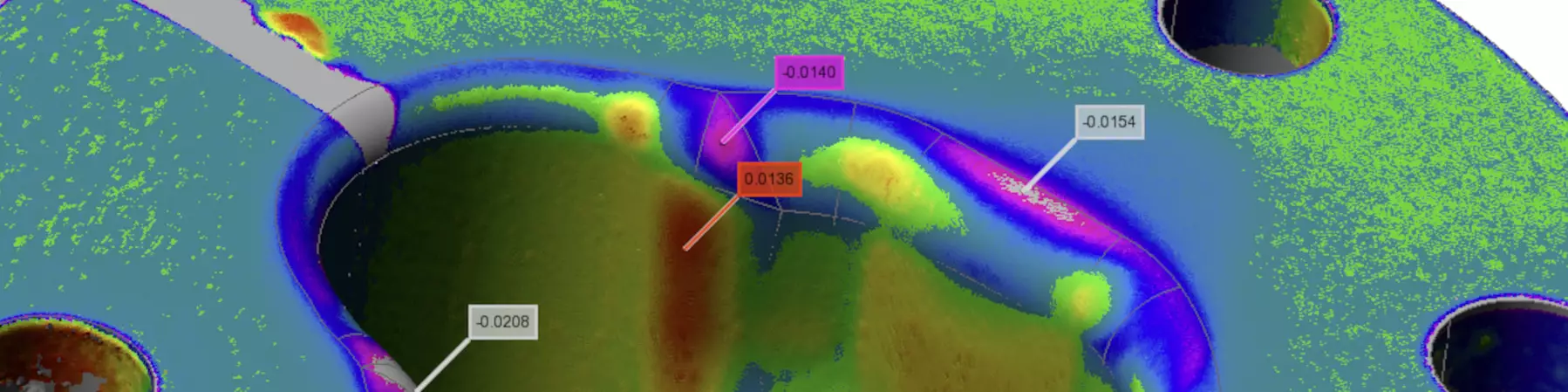
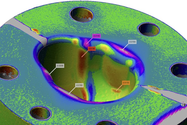
Reverse engineering of new molds to reduce the number of iterations requires scanning the mold and the plastic parts (sometimes a shop can use a nominal mold model), then using point cloud software to map the plastic part data onto the mold. This step shows the deviations that are occurring versus expectations.
Modern point cloud software allows a shop to take the deviation and map the opposite onto the mold model (as an STL file). Basically, the location of sink in a part indicates where to remove material in the mold. The software indicates a 1:1 modification or any other necessary ratio. So, if an area of a plastic part has sink that equals 0.0005 inches in depth, the moldmaker must move the steel by 0.0005 inches. A moldmaker's familiarity with the material and its behavior will allow him to alter this ratio (1:1.06, for example) to compensate the steel by a greater or lesser amount.
Once the moldmaker updates the STL file, he can converts the file to a NURBs model file for export as STEP, IGES or parasolid. To save time, only extract the areas being modified and sew them into the original CAD model as surface patches.
Using scanning technologies to look at an entire part (as opposed to only discrete locations), a moldmaker can more easily accommodate minor oddities that occur with injection-molded parts. If a shop needs to make further iterations, repeat this process only in the areas that are still out of specification.
If a mold builder's internal resources are tight, seek a qualified outside service provider with both scanning and freeform modeling expertise to perform these reverse engineering steps.


Related Content

Precision Welding Services Offer Rapid Turnaround Mold Repair and Reduced Molder Downtime
X-Cell Tool & Mold relies on outsourced, high-quality welding repairs from Lewis-Bawol Welding to ensure its customers' molds are back in production quickly and affordably.
Read More
Predictive Manufacturing Moves Mold Builder into Advanced Medical Component Manufacturing
From a hot rod hobby, medical molds and shop performance to technology extremes, key relationships and a growth strategy, it’s obvious details matter at Eden Tool.
Read More
How to Use Thermal Management to Improve Mold Cooling
A review of common mold cooling issues and possible solutions, including 3D printing applications.
Read More
Hands-on Workshop Teaches Mold Maintenance Process
Intensive workshop teaches the process of mold maintenance to help put an end to the firefighting culture of many toolrooms.
Read MoreRead Next

Inspection/Measurement Software Helps Hyatt Die Cast and Engineering Reduce Costs While Increasing Efficiency and Quality
Hyatt Die Cast and Engineering Reduces Manufacturing Costs While Increasing Efficiency and Quality with Integrated Inspection/Measurement Software.
Read More
Improve Overall Inspection with Automated Measurement
Automated shop floor inspection and measurement technologies are leading mold builders to smart manufacturing.
Read More
A 'Quality Without Compromise' Mindset and A Diverse Customer Base Gives Delta Mold More Peaks Than Valleys in Business
Quality-driven processes and focus on diversity in the markets served are key to Delta Mold’s continued success.
Read More