


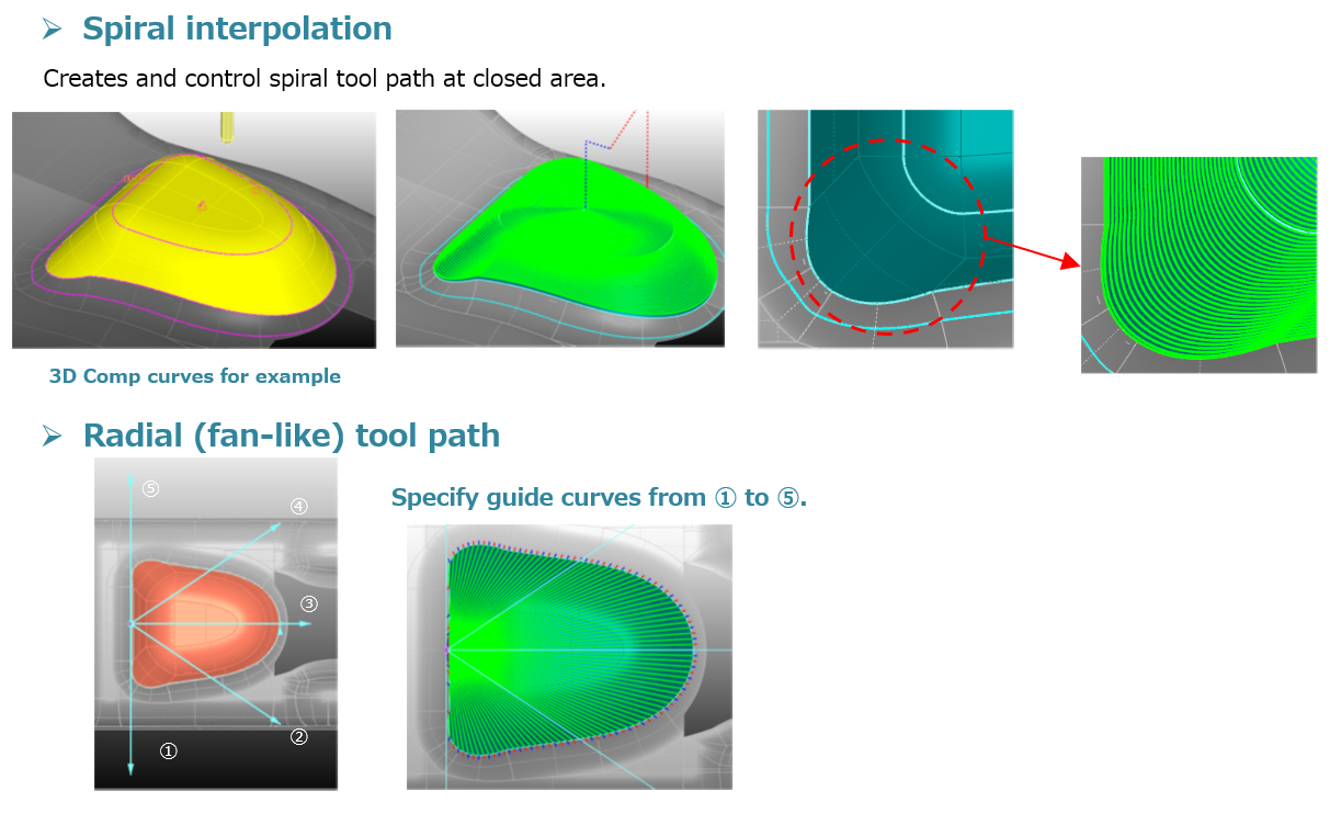
Using guide curves will enable mold builders to generate a variety of tool paths based on the user’s needs instead of the one generic toolpath option most software offers.
Photo Credit, all images: CGS North America (CAM-TOOL)
When it comes to CAM programming, the goal is to use the supplied CAM software to output quality tool paths while considering tolerance, runtime, machine and tooling capabilities and many other variables. Oftentimes, users feel the easiest tool path to create is the best option. Basic CAM software has sufficient toolpath strategies that enable many machined parts to meet a programmer’s needs, but this is not always the case. For example, cases that require no compromise for part accuracy and surface finish call for specialized programming strategies offered by a select few CAM software providers.
Every CAM programmer is familiar with basic toolpath strategies, such as roughing, re-roughing, Z-level finishing, planar (scan) finishing, flat surface and remachining. While a programmer can “make it work” with these tool paths when machining most parts, other software offers strategies — although used less often — that are invaluable in the right circumstances. For example, advanced strategies that use composite curves and surfaces, a surface to “aim” a tool path onto a part or cylindrical surfaces to produce the perfect thread for the molded plastic part.


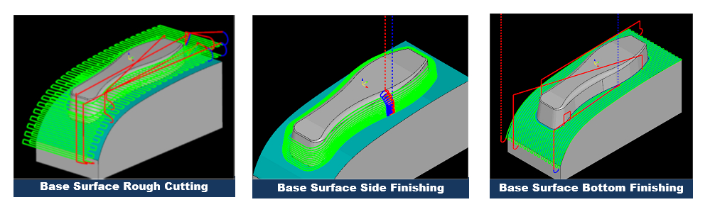
Base surface tool paths follow a base surface for direction, enabling mold designers to create surfaces to drive tool paths in the way they choose.
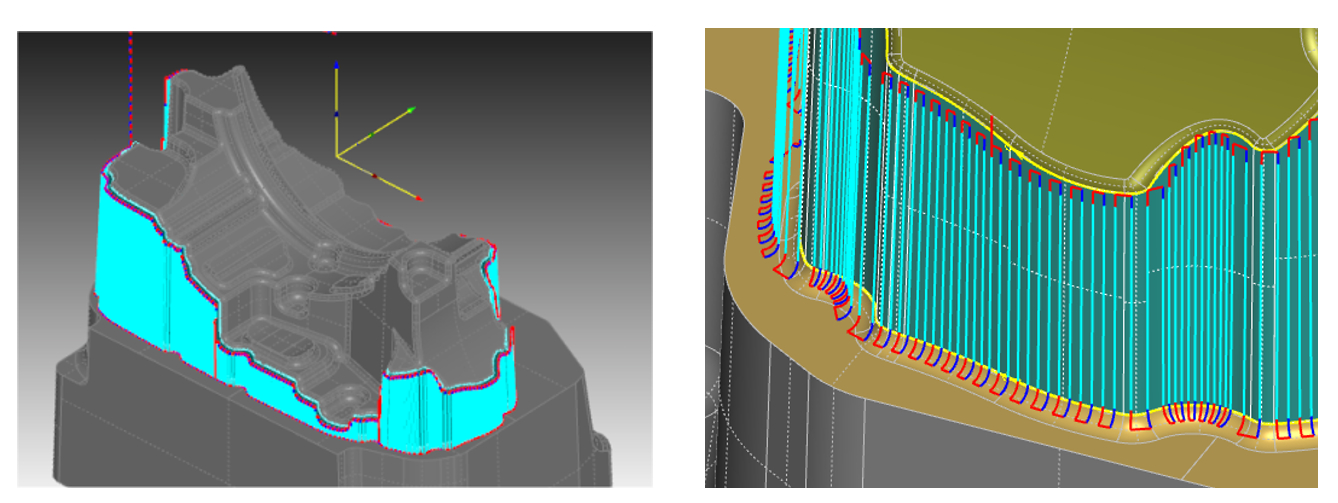
The term “projected tool path” refers to a programming strategy that allows the user to generate a tool path on a simple surface created by the programmer and then project that tool path onto more complex surfaces.
Any programmer will admit that the software does not always generate the ideal tool path even when good strategies are implemented. However, whether the issue is the order, direction or smoothness, the programmer can always do something to get that “perfect” tool path. Also, having the tools at their disposal to change each aspect of a tool path after it is generated offers a significant advantage to the programmer.
Projected Tool Path

To machine an earpiece mold, specific cut directions are required by the customer to achieve the desired results.
Recently, a North American plastic injection mold builder wanted to improve the current surface finish on an optical part, but the current CAM system had shortcomings, such as the unpredictability of the remachining tool path in intricate areas of the part, and the inability to control the direction and order of the tool path. These issues resulted in a mediocre finish that was inconsistently passing customer specifications.
The moldmaker moved to CAM software that used “projected tool path” and could obtain a consistent stepover and manipulate the order and direction of specified path segments. The ability to make changes to the tool path without needing to recalculate the entire path is a huge advantage. However, being able to cut in a uniform direction while maintaining a consistent stepover proved beyond the software’s ability.
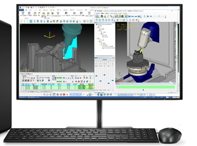
Machine simulation inside CAM software offers machine verification for complex tool paths, ensuring safety before they run at the machine.
The term “projected tool path” refers to a programming strategy that enables the user to generate a tool path on a simple surface created by the programmer, and then project that tool path onto more complex surfaces. The advantage is that it forces the tool path into a uniform stepover that would be extremely difficult for the software to generate using the original complex surfaces. These types of tool paths can also be used to protect surfaces and ensure proper blending.
After projecting the uniform tool path onto the surface, the moldmaker wanted to change its direction and order to test the results. This task — which some CAM software cannot accomplish and would force others to recalculate — was completed simply by entering the toolpath editor, selecting the paths and reversing the direction. The order of the paths was similarly changed and a completed program was quickly ready for posting.
Plunge rough tool path generated around a part using curves to vertically cut steep walls instead of a traditional Z-level approach.
Proven Results
As a result of implementing these advanced toolpath creation methods, the customer met and exceeded the objectives laid out prior to the test cut. By perfecting the tool path using advanced strategies in a high-level CAM system, the mold builder also improved surface finish quality, surface finish consistency and cutting tool life.
Having the right CAM tools at their disposal to change each aspect of a toolpath after it is generated offers a significant advantage to the programmer.
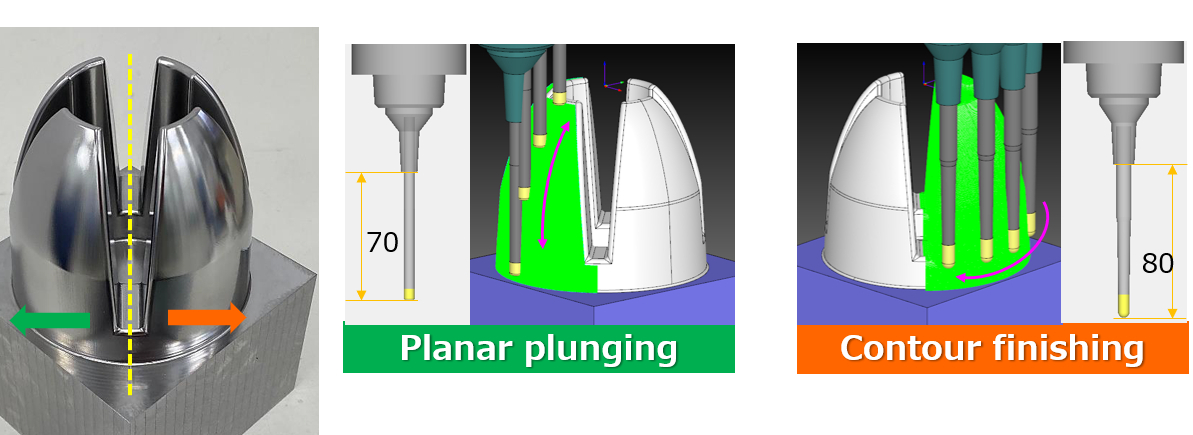
Various machining options offer ways to manipulate plunge toolpaths to yield the desired results.
In another case, a customer gave a specification sheet to a mold builder which outlined the method, direction and order of cut in detail. A CAM system that can generate a simple path and then edit that path to meet these standards gives the programmer a significant advantage over one that does not.
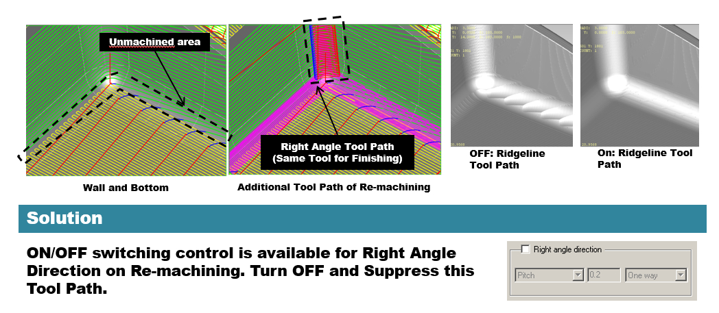
Right angle control enables users to have the option of how they want to approach the steel in remachine toolpaths, depending on the geometry they are cutting.
For instance, making complicated boundaries, maintaining equal pitch and recalculations are all challenges programmers can encounter when the right CAM system is unavailable. Time is money, and all those difficulties can cause long delays that no one can afford.
As customers become more demanding as to the quality of parts coming off the machine and the technology of the CNC machines continues to grow, it is vital to upgrade your CAM system to meet these requirements. The saying “A chain is only as strong as the weakest link” holds true for CNC machining, so make sure your CAM system is not the weakest link in your process chain.
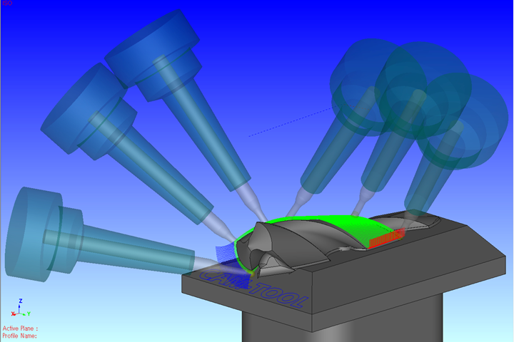
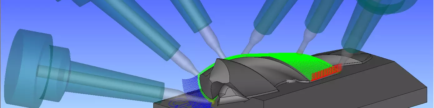
An example of a complex five-axis toolpath generated around a drill body, showing the control accomplished by using curves to manipulate a toolpath.


Related Content

Plastic Prototypes Using Silicone Rubber Molds
How-to, step-by-step instructions that take you from making the master pattern to making the mold and casting the plastic parts.
Read More
Laser Welding Versus Micro Welding
The latest battle in finely detailed restoration/repair of mold materials.
Read More
Machining Center Spindles: What You Need to Know
Why and how to research spindle technology before purchasing a machining center.
Read More
Maintaining a Wire EDM Machine
To achieve the ultimate capability and level of productivity from your wire EDM on a consistent, repeatable and reliable basis, regular maintenance is a required task.
Read MoreRead Next

Surface-Based CAM System for High-Accuracy 3D Machining
CAM-Tool by CGS North America is backed by a variety of toolpath options and a comprehensive support team. The company will be exhibiting at IMTS 2022.
Read More
IMTS 2022: From Precision Products & Professionals to Podcasts & Parties
Four years since the last IMTS and this 2022 event served up plenty of product line expansions, technology enhancements, candid conversations about business challenges and deep discussions about using technology and training to stay competitive.
Read More
Are You a Moldmaker Considering 3D Printing? Consider the 3D Printing Workshop at NPE2024
Presentations will cover 3D printing for mold tooling, material innovation, product development, bridge production and full-scale, high-volume additive manufacturing.
Read More