
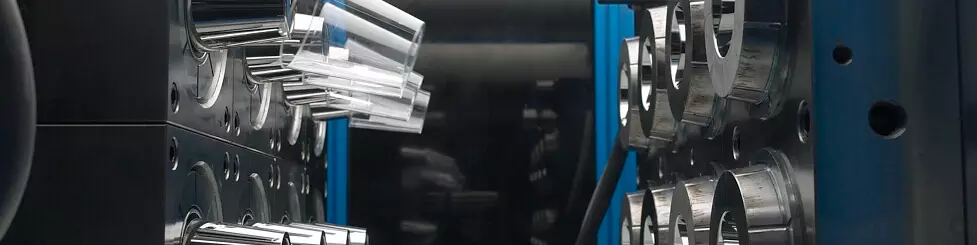


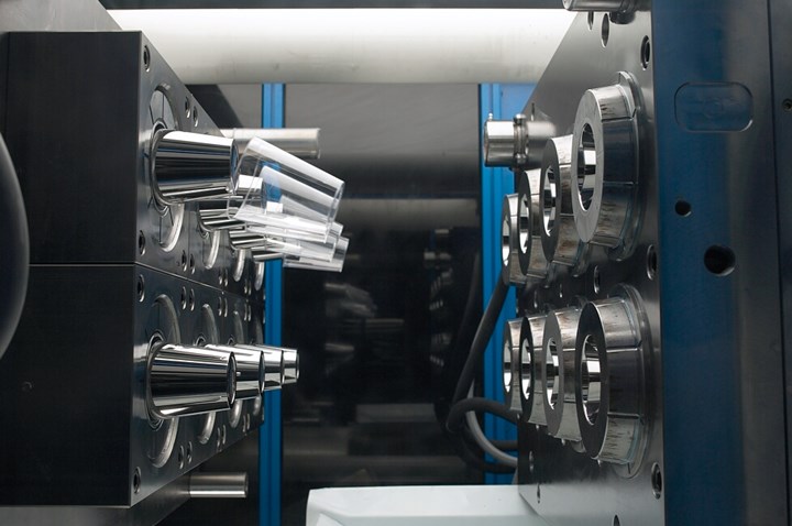
A mold designer can reduce the impact of a potential mismatch and ease the cost of building a mold with simple modifications to the mold design. Source (All Images) | Oasic Consulting
Trying to produce a perfect match between two surfaces is not only difficult to achieve but also very costly. Mold designers create deliberate mismatches for ease of manufacturing and improved part aesthetics.
There are two areas of deliberate mismatch to consider. One is between the core and cavity and the other is between the two matching plastic parts. There are many variations of matching parting lines or between lids and covers, but the basic principle applies to all of them.


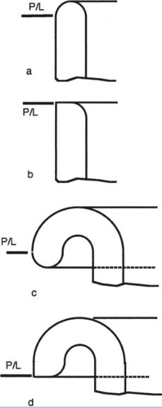
Figure 1. Typical round edges where a mold designer could consider a sharp edge (parting line = P/L).
Round Edge or Sharp Edge?
A mold designer must first consider whether a rounded edge (see Figures 1a and 1c) is necessary at the end of a part and the parting line. While it may be more aesthetically pleasing to have a rounded edge, in most cases, it causes much more complexity and tighter manufacturing tolerances, especially in high-cavitation molds where cores and cavities must be interchangeable.
A rounded edge causes the potential of a mismatch to be much more pronounced as the diameter on the core side must equal the diameter on the cavity side just after a radius on the part. If a rounded edge is necessary, then a small straight diameter of at least 0.25 millimeter (0.010 inch) should be added to the side with the radius before the parting line, so that a more stable diameter can be achieved to match the opposing mold side.
Suppose a sharp edge (see Figure 1b or 1d) is acceptable for the application. In that case, the potential of an undesirable mismatch is virtually eliminated and the cost of high-tolerance manufacturing is significantly reduced.
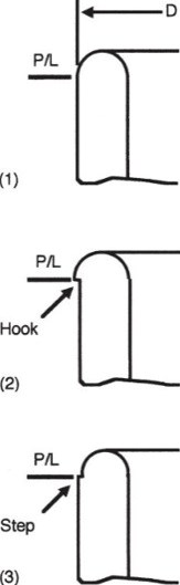
Figure 2. Round edge options include (1) ideal (2) with hook and (3) with step.
If a round edge is necessary, then there is a solution to reduce the visual and manufacturing impact of trying to create a perfect match. Figure 2 shows one of several designs of a round edge with the ideal case having a perfect match at the parting line (1). However, due to the buildup of manufacturing tolerances of the mold parts and variations in stacks in multi-cavity tools, such an ideal case is not practical. In reality, the nominal diameter D of the cavity, or the core, will be either larger or smaller than the matching one and create either a hook (2), which is generally not tolerable, or a small step (3), which in most cases is perfectly acceptable.
Note that the actual differences caused by the tolerances of the diameters are small, usually less than 0.1 millimeter (0.004 inch), so that a step would not be more than about half this amount. However, a step is much less noticeable than a hook and it does not create the feel of a sharp edge or a flashed mold.
If required, a significant mismatch can be corrected by very time-consuming handwork, grinding or stoning (polishing). However, this should be avoided because of the high cost and difficulty in repeatability and core/cavity interchange possibilities on multi-cavity molds.
The proper and most economical approach is to dimension the matching diameters so there is always a step of a magnitude between zero and 0.1 millimeter (0–0.004 inch), as seen in Figure 2 (3).
If the mismatch is located where the consumer uses their hand or lips, then the location of the mismatch must be verified with the molder or OEM to ensure this will not be a problem once molded. It may be preferable to offset the mismatch in one direction or another to hide it.
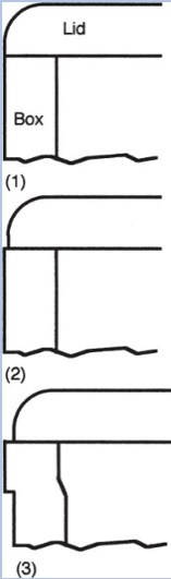
Figure 3. Mismatch avoidance options between the box and the lid.
Mismatch Between Two Matching Pieces
The conditions of a mismatch are similar when designing and building molds for matching containers and lids. Here, a deliberate mismatch is even more important because the products may come from different cavities or even molds made under varying molding conditions. Also, due to the buildup of many tolerances (in cavities for both products), the mismatch could be much larger.
Figure 3 (1) shows the ideal condition that is difficult or impossible to achieve on multi-cavity molds. Figure 3 (2) shows a way to minimize the effect of a mismatch between matching parts without causing an unsightly and poor-quality overhang of the lid from the container. Adding a decorative band to the larger part, as shown in Figure 3 (3), is another way to create an aesthetically pleasing look that reduces the visual impact of the mismatch.
A mold designer can reduce the impact of a potential mismatch and ease the cost of the mold build by considering these simple modifications to the mold design in the concept and plastic part design stage.


Related Content

How to Select a Mold Temperature Controller
White paper shares how cooling channel analysis, which collects maximum pressure drop, total flow rate and heat dissipation, eases the performance evaluation of mold temperature controllers.
Read More
Leading Mold Manufacturers Share Best Practices for Improving Efficiency
Precise Tooling Solutions, X-Cell Tool and Mold, M&M Tool and Mold, Ameritech Die & Mold, and Cavalier Tool & Manufacturing, sit down for a fast-paced Q&A focused on strategies for improving efficiencies across their operations.
Read More
OEE Monitoring System Addresses Root Cause of Machine Downtime
Unique sensor and patent-pending algorithm of the Amper machine analytics system measures current draw to quickly and inexpensively inform manufacturers which machines are down and why.
Read More
Mold Design Review: The Complete Checklist
Gerardo (Jerry) Miranda III, former global tooling manager for Oakley sunglasses, reshares his complete mold design checklist, an essential part of the product time and cost-to-market process.
Read MoreRead Next

Tolerancing in Mold Design, Part 2: Using GD&T to Address Conventional Tolerancing Issues
Mold designers can achieve a single interpretation of workpiece functionality when following the American Society of Mechanical Engineers Geometric Dimensioning and Tolerancing standard.
Read More
MMT Chats: Giving Back by Answering the Moldmaking Education Need
MoldMaking Technology Editorial Director Christina Fuges checks in with Bruce Cateon, an executive advisor at OASIC Consulting. Bruce started out in moldmaking, eventually becoming an industry consultant and taking time to work on his passion project the “Injection Mold Design Handbook” as a way of giving back to the industry that has given him so much. This episode is brought to you by ISCAR with New Ideas for Machining Intelligently.
Read More
It Starts With the Part: A Plastic Part Checklist Ensures Good Mold Design
All successful mold build projects start with examining the part to be molded to ensure it is moldable and will meet the customers' production objectives.
Read More