

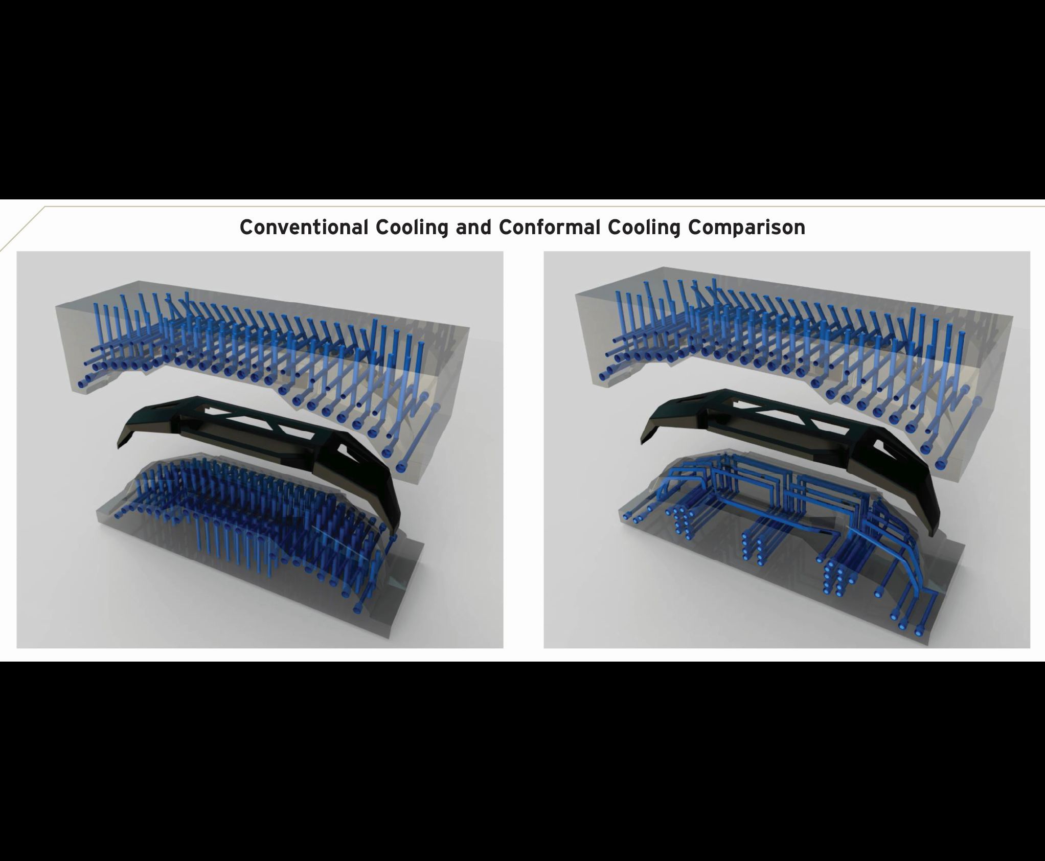
These renderings illustrate coolant hole layout for a conventionally cooled core and cavity for a bumper mold (left) and a conventionally cooled cavity and a conformal-cooled core of a bumper mold. The conventionally cooled core required more than 100 holes and baffles while the conformal-cooled core required only 30 holes and baffles. Cooling channels follow the surface contour of the core face allowing maximum coverage to evenly and quickly cool the molded part. Note that the amount of available area in the conformal-cooled core would give designers the flexibility to add lifters and slides. Images courtesy of Conformal Cooling Solutions.
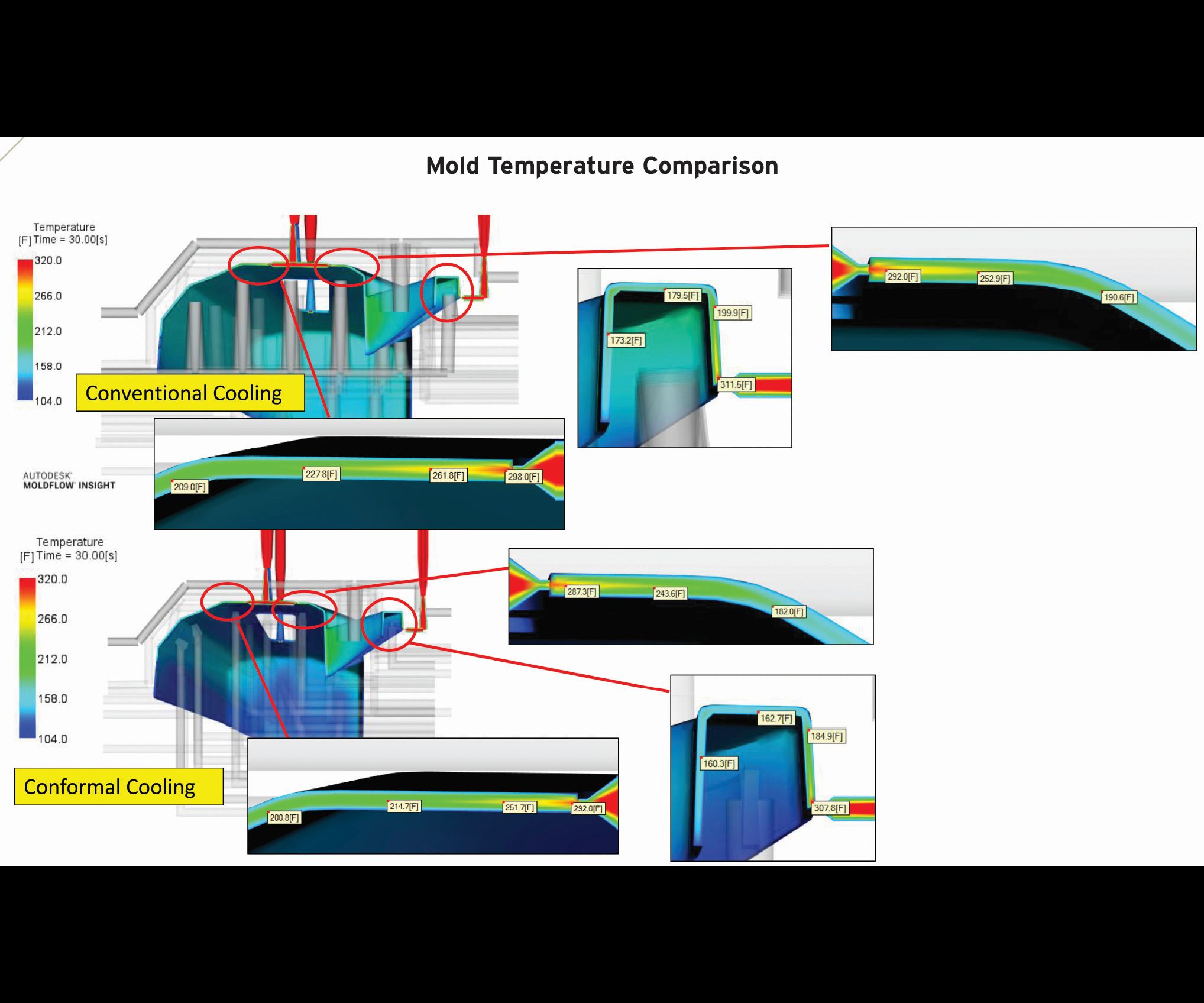
The results of a temperature analysis of a conventionally-cooled and conformal-cooled bumper mold show the part temperatures through the thickness after the 30-second cycle time. Note that the average temperature delta is 19°F to 23°F between both cooling methods. This allows part ejection at lower cycle times without affecting part quality. Note the temperature difference at the nozzle outlet, which is typically the last area to cool.
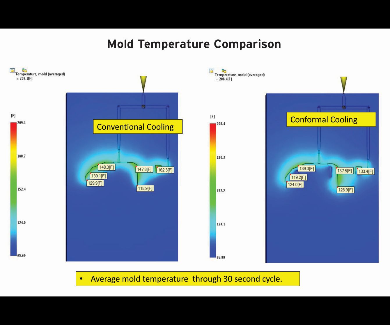
Results show the mold surface temperature after a 30-second cycle time. Note the average temperature delta between the conventional and conformal methods is 9.3°F, allowing more even heat distribution and faster part cooling.
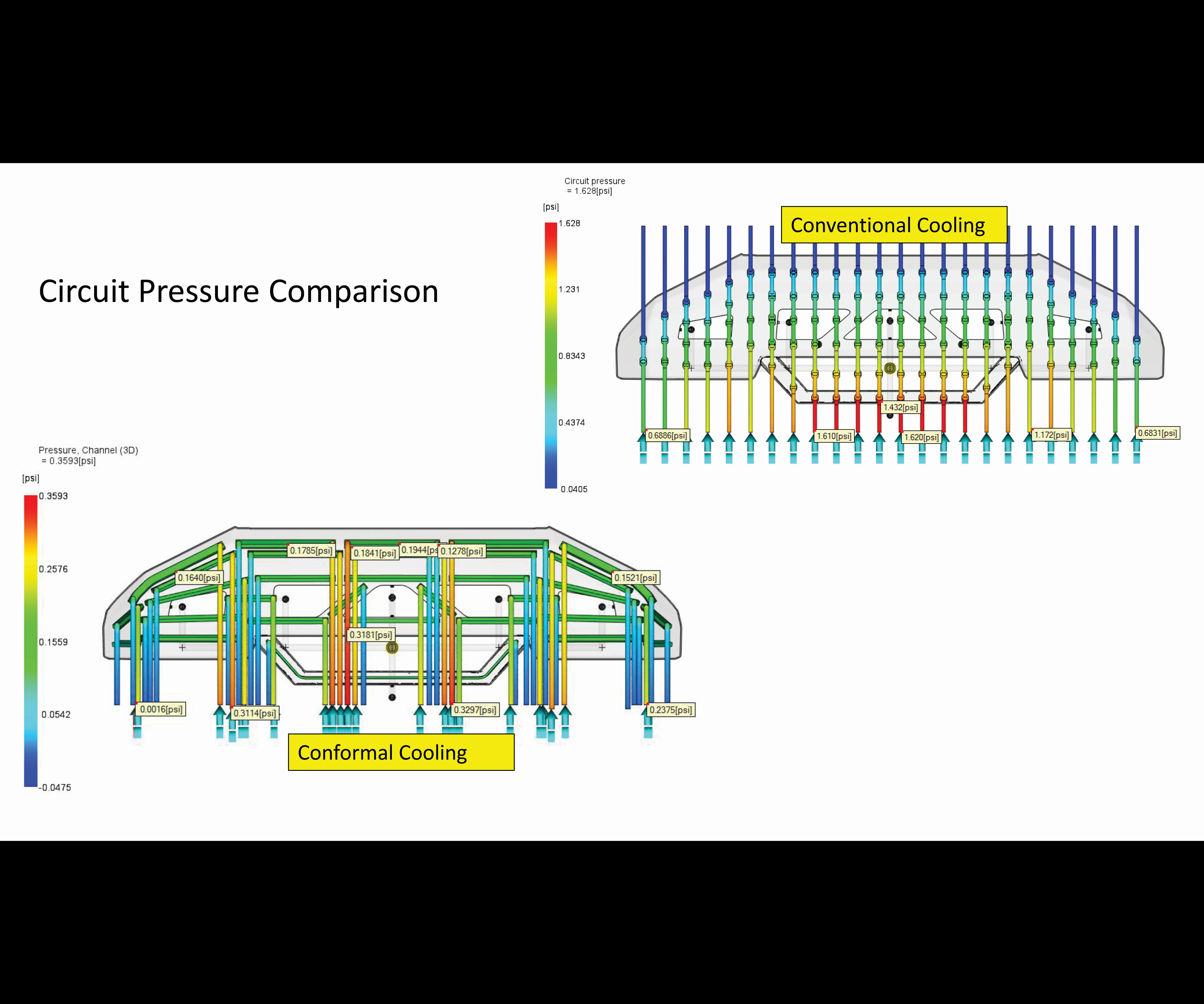
A reduction in circuit pressure yields less wear and tear on pumps and can reduce energy usage. Note the circuit pressure reduced from 1.628 psi for the conventionally cooled core (left) to 0.359 psi for the conformal-cooled core (right), using a flow rate of 2.65 gpm.
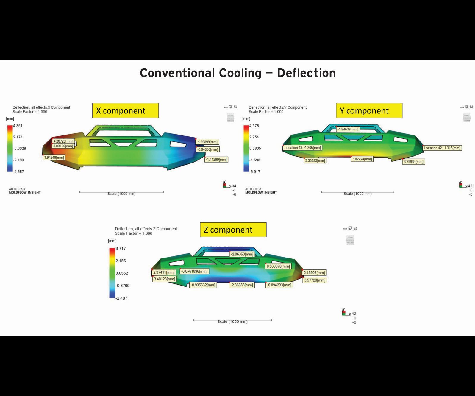
This part deflection study of the conventionally cooled bumper mold shows the deflection of the molded part in the various planes. The X plane shows more uneven shrinkage at the ends of the part, which are typically difficult to cool. Note the uneven shrinkage across the part face, which could show as a wave pattern in the finished part. The Y plane shows the part deflecting along the bottom edge, causing the part to frown. The Z plane shows the ends being pushed inwards in the midsection and outwards at the ends. This condition will make installation more difficult during assembly.
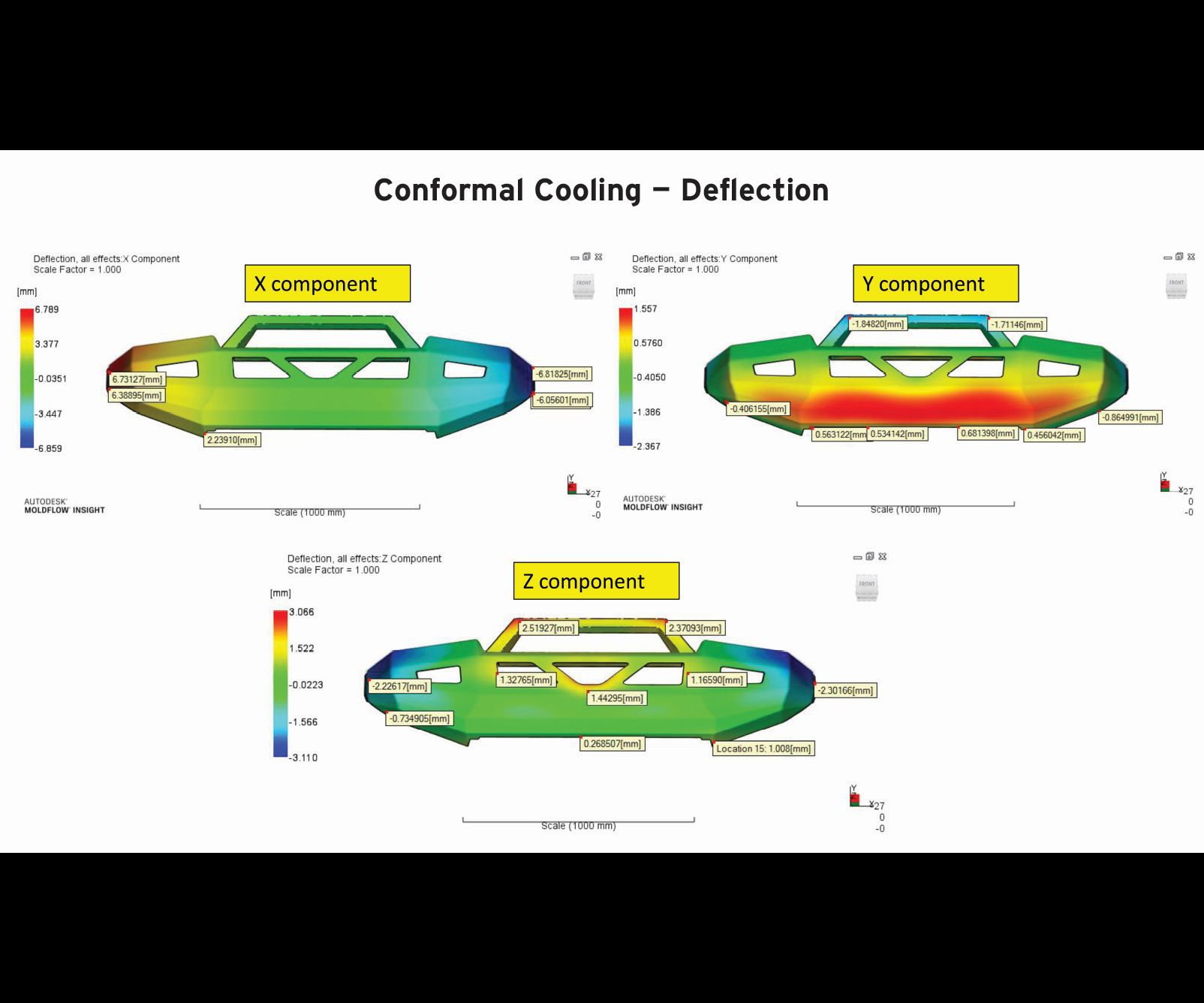
This part deflection study of the conformal-cooled bumper mold shows the deflection of the molded part in the various planes. The X plane shows more even shrinkage across the part, minimizing warpage (including the ends of the part). The Y plane has the part being more evenly cooled in the midsection and across the face. It also shows the part being pulled towards the cavity due to the effective cooling of the core, which assists with demolding. The Z plane shows the part maintaining an even deflection with minimal warpage. Note that the ends are deflecting inwards, which eases installation during assembly.
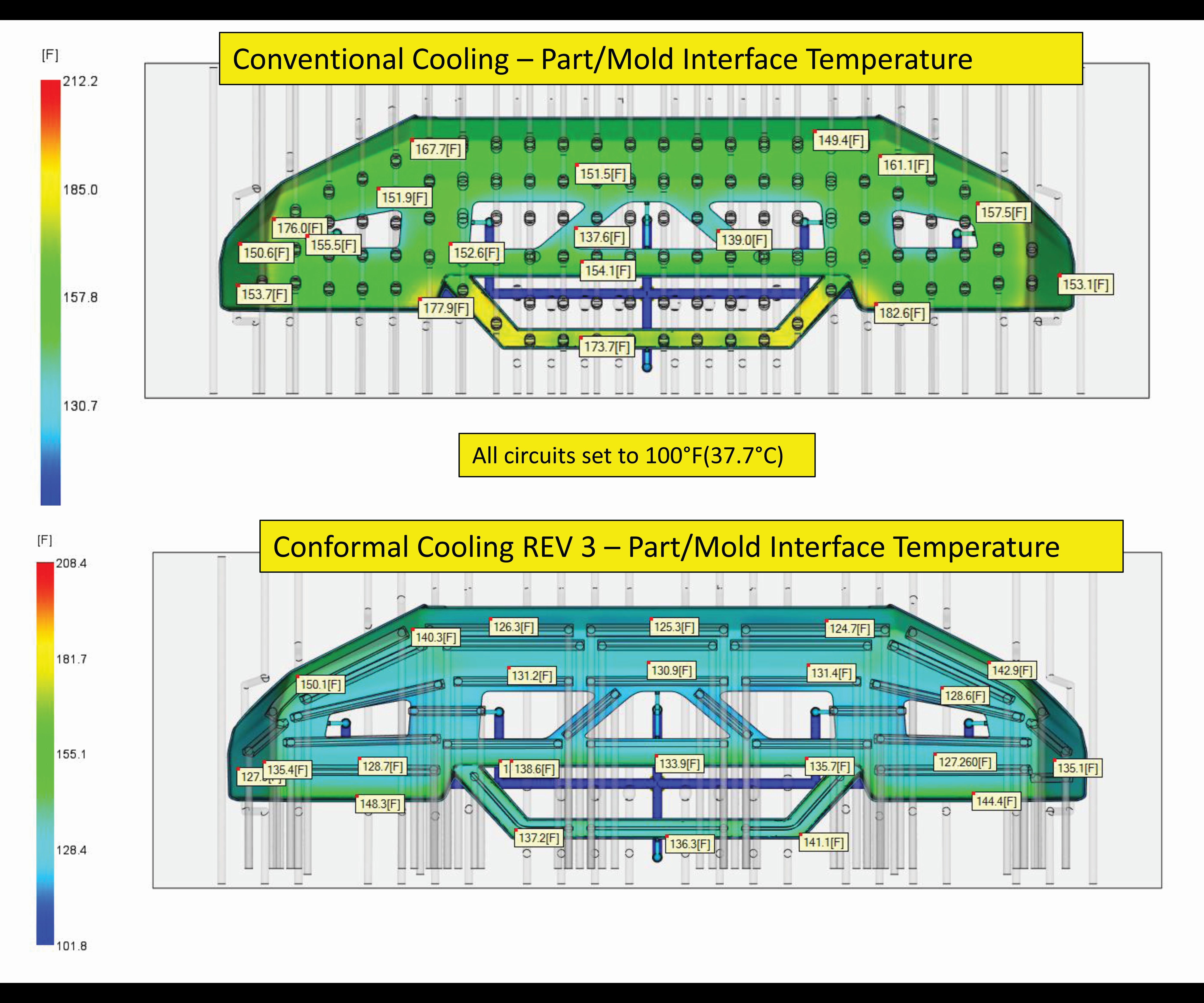
A reduction in the part/mold interface temperatures occurred once the mold circuit temperature stabilized to 100°F. Using a sampling average from left to right, note the average 25.5°F-reduction in temperature, which reduces cycle time by allowing ejection at lower temperatures. Note the more even temperature gradient with the conformal cooling process, which offers more consistent dimensional stability, reduced cycle times, minimized local hot spots, faster production startups and less wasted material during startup.


Injection molds for automotive fascia bumpers, wheel liners and instrument panels have multiple sweeping contours. During the manufacturing of a mold, the cooling design will significantly determine the cycle time. A newly patented conformal cooling technique has been developed that can greatly reduce cycle time by improving the cooling process while enhancing part quality, decreasing electricity and labor usage, and adhering to health and safety practices. The process uses a multilayer robotic deposition additive manufacturing technology.
Six years of collaboration among welders; mechanical, electrical and software engineers; and graduate students from the University of Waterloo, along with private and government-granted funding, enabled the development of an additive metals technology to create an accurate 3D object on an existing 3D contour surface. This research ultimately led to an advanced method for achieving conformal-cooled molds. Here, we’ll examine the evolution of this technology by reviewing control and consistency benefits.


Technology Evolution
Manual TIG welding has its shortcomings, according to Pat Zaffino, managing director for Conformal Cooling Solutions Ltd. For example, it is prone to weld imperfections on the mold surface, such as pin holes, porosity, surface cracks and weld hard lines. The tungsten electrode used may be contaminated several times per hour, which affects weld quality and increases costs. It is also very difficult to create 3D objects manually with this process. Typically, skilled welders can only deposit 0.75 pounds of weld per hour, cannot create two identical weld beads (inherent variation occurs) and are exposed to extreme temperatures (450°F to 750°F) when welding on large molds, which poses safety and comfort issues.
Zaffino was especially concerned about the safety issues of the manual TIG welding process. “Sure, there are welding blankets that cover the mold; however, no matter how you try to keep the welder cool, that heat dissipates up. It becomes a real health and ergonomic hazard.” This inspired him to create a process that would make welding safer and more comfortable for his employees. The resulting 3D robotic deposition system takes the welder away from the very hot mold and eliminates a very difficult manual welding process.
For this system, the team developed a process that reads CAD files to locate the required surfaces and the 3D volumes to be added to a mold, then determines the required deposition paths and arc parameters, which is forwarded to the robotic cell. In the robotic cell, the operator locates the pickup points on the mold (tooling ball). Then the robotic software interpolates the paths to create layers of tool steel beads on a 3D-contoured mold surface, controlling factors such as end-of-arm deposition angle, wire feed and temperatures.
It does this exactly as a welder would, while knowing where the robot is in relationship to the mold surface.
It does this exactly as a welder would, while knowing where the robot is in relationship to the mold surface. Basically, the team developed code functions similar to a CNC machine, except to add material instead of to remove it. The deposition process is performed in layers. For example, where multiple objects are being created, the deposit of tool steel materials can also be completed on each object one at a time. This helps to minimize distortion and residual stress of the object and the mold.
These features and functions enable the multilayer robotic deposition system to deposit up to 2.5 pounds of tool steel alloy per hour, creating consistent and reproducible beads, while eliminating defects and reducing issues related to extreme temperatures. Through his past experience, Zaffino claims that in manual TIG welding, the welder tends to contaminate the tungsten as many as six times per hour by touching the steel, which affects quality and cost. With the robotic deposition system, a single sharpening of the tungsten electrode has been able to endure up to 8 hours of depositing tool steel alloys.
Application Evolution
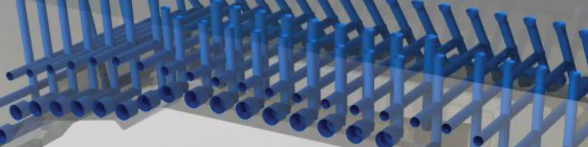
“Once we were able to create near-net-shaped objects on an existing 3D surface, we started to develop the technology further to produce conformal cooling water circuits using the same 3D format,” Zaffino says. Current mold cooling technology for a bumper mold could require 50 to 100 baffler/bubbler holes, which are drilled from the bottom of the mold up toward the molding surface where coolant passes through the baffle system. The drilling is time-consuming and uses an enormous amount of space in the mold, which limits a designer’s ability to place other mechanisms, such as lifters and ejector pins into the mold.
Using this robotic multilayer deposition system for conformal cooling can eliminate the majority of the baffles or bubbler systems, which in turn, reduces gun drilling and tapping by 75 percent.
Using this robotic multilayer deposition system for conformal cooling can eliminate the majority of the baffles or bubbler systems, which in turn, reduces gun drilling and tapping by 75 percent, according to Zaffino. This increases design flexibility for other mold mechanisms and permits cooling channels in the core half of a mold. Cooling channels can also be placed in the lifters and slides and can closely follow the surface contours for maximum cooling effectiveness.
A channel is machined in the core molding surface and the multilayer deposition system closes this channel to create a closed chamber for water flow. The channels are now a consistent distance from the molding surface, which provides predictable cooling of the mold surface and reduces cycle time.
The most efficient way to deposit any alloy, Zaffino says, is in the flat position, so that gravity is not a factor. The conformal cooling channel is orientated by the system, so it is perpendicular to the floor. This ensures that the bead sequence is consistent within the channel. There are set standard operating procedures within the system. For example, if the channel receives 24 beads for a 0.750-inch channel, there will be 100 percent consistency for all similar channels of the same dimension. The only variation would be the length of the channel. For this process, 0.500- and 0.625-inch channels have been implemented.
A simulation study was conducted using Autodesk MoldFlow Insight to determine the impact of conformal cooling channels produced via the multilayer robotic deposition system. The findings report that conformal cooling created a more even temperature across the molding surfaces, reducing cycle time and improving part quality; circuit pressure with conformal cooling reduced pressure by a factor of 20 times throughout the circuit; and, the mold interface temperature with conformal cooling resulted in a 25.5°F-temperature reduction, better dimensional stability, the elimination of hot spots, quicker production startup and less material waste.
The mold interface temperature with conformal cooling resulted in a 25.5°F-temperature reduction, better dimensional stability, the elimination of hot spots, quicker production startup and less material waste.
In addition, a part deflection study indicated more even linear shrinkage across the length of the part, and more even cooling across the center portion of the part that featured the largest surface area. Finally, the study found more even distortion in the Z plane and minimized warpage.
This patented process was tested and proven in a mold that has produced more than 20,000 fascia bumpers. The cycle time was reduced by 25 percent compared to the conventionally-cooled mold. “We are encouraged by these results and believe that it could greatly benefit molders through improved cycle times, provide better part quality, increased press utilization rates and decreased energy use,” Zaffino says.


Related Content

Plastic Prototypes Using Silicone Rubber Molds
How-to, step-by-step instructions that take you from making the master pattern to making the mold and casting the plastic parts.
Read More
VIDEO: How can 3D Printed Tooling Improve Injection Mold Venting?
Proper venting is one of a mold builders toughest challenges as molders struggle to keep vents free flowing in production. Learn how to apply 3D printing to mold venting and the benefits of additive venting inserts.
Read More
Evaluating Metal Powders for Conformally Cooled Mold Inserts
Mechanical properties and design software techniques reveal the benefits of a modified high thermal conductivity metal powder for 3D printing in moldmaking.
Read More
MoldMaking Technology's Most-Viewed Content 2022: Products
MMT shares the five top-viewed technologies, equipment and services of 2022 in each Engineer, Build, Maintain and Manage tenet based on Google Analytics.
Read MoreRead Next

Financial Justification of Conformal Cooling
A ratio analysis helps illustrate the estimated effects of conformal cooling on profitability.
Read More
Reasons to Use Fiber Lasers for Mold Cleaning
Fiber lasers offer a simplicity, speed, control and portability, minimizing mold cleaning risks.
Read More
How to Use Strategic Planning Tools, Data to Manage the Human Side of Business
Q&A with Marion Wells, MMT EAB member and founder of Human Asset Management.
Read More