
Rapid Tooling Via Stereolithography Gets a Closer Look
Industry roundtable reports initial findings.


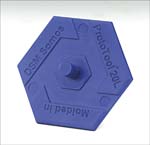
Figure 1. ABS part molded directly from ProtoTool™ 20L (a strong, stiff, composite SL resin) mold. Figures courtesy of DSM Somos.
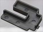
Figure 4. ABS part molded directly from Nanoform™ (a strong, stiff, nanocomposite SL resin) tool.
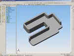
Figure 2. Part design for rapid tooling development initiative.
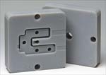
Figure 3. Nanoform™ mold built with cooling channels.
Approximately two years ago, composite stereolithography (SL) resins were introduced to the marketplace, offering performance features beyond what traditional SL resins could offer. In particular, the high heat deflection temperatures (>500°F) and high stiffness of these highly filled resins have opened the door to several new rapid prototyping (RP) applications, including wind tunnel test modeling and, more recently, rapid tooling.
In rapid tooling applications, molds made from composite SL resins have been able to successfully produce hundreds of injection molded parts at a time from such plastic materials as ABS, polypropylene, polyethylene, polycarbonate, thermoplastic elastomer and 33 percent glass-filled nylon. Depending upon part geometry, the use of these composite molds provides time and cost savings as compared to machined metal molds.
Rapid tooling via stereolithography, however, is still a novel technology with many questions remaining regarding tool size and geometry limitations, tool life expectancy and dimensional stability. To address these questions, key players in the rapid prototyping and rapid tooling industries from around the country have recently joined a rapid tooling roundtable initiated by a global SL resin supplier.
The roundtable is currently completing the first controlled studies to better assess SL rapid tooling technology for its accuracy and reliability both in build parameters and the molded parts, as well as to evaluate its cost effectiveness as compared to other rapid tooling methods. Initial Phase 1 findings are reported here.
Background: Creating Composite Molds Via Stereolithography
Stereolithography is an additive process by which a computer (CAD) image is grown into a physical 3-D object via a vat of photo-curable liquid resin and a laser. As the laser draws each successive cross-section of the image in the vat, the resin is solidified layer by layer from the bottom up.
Layer thicknesses range from 0.002"to 0.006" depending on the type of equipment and laser used. The smaller the layer thickness, the higher the resolution—though the longer the build time. For example, parts created with a 0.002" layer thickness can take more than nine hours to build versus just a four-hour build time at 0.006". Whenever possible, a layer thickness of 0.004" or greater is recommended.
After a composite SL mold is built, post-processing is required. The part is removed from the vat and cleaned with a solvent to remove any excess uncured liquid resin that may be adhering to the mold’s surface. The mold is then post-cured in a chamber with UV light for approximately 30 minutes on each side, after which it is ready for finishing.
Finishing of SL composite molds can be accomplished using conventional methods, such as machining, grinding or hand sanding (wet or dry). If significant amounts of machining are required, carbide tools are recommended. A mixture of dishwashing soap and water works well as a cutting fluid. For accuracy, it also is recommended that holes for ejector pins, core pins, etc. be built directly in the mold halves. They should be slightly undersized and then reamed for a perfect fit.
Benefits of SL Composite Molds
Parts built via stereolithography are currently used as concept models, fit and function prototypes, patterns for cast urethane molds, and now rapid tooling. For moldmakers, the stereolithography process offers several benefits. In addition to requiring minimal labor (the build process is completely automated once the CAD file has been loaded into the system), the resolution—and therefore the detail—obtained via stereolithography is excellent. Details that would be difficult to machine can be easily built into an SL mold (see Figure 1).
Another benefit is the size of the SL machine’s platform, which ranges from 10"x10" to 20"x20"; therefore, allowing multiple mold inserts to be built simultaneously, or hand-loaded inserts to be built in conjunction with the core and cavity, for greater efficiency in the mold shop.
Phase 1 of Rapid Tooling Round Table Study: Preparing SL Molds
In Phase 1 of the rapid tooling roundtable development initiative, a small, simple yet representative part was designed by the group (see Figure 2). Using this part design, molds were made via several tooling methods including stereolithography, CNC machining and cast epoxy. Each tool set will then be used to injection mold parts out of ABS, after which part quality, dimensional stability, cycle time and tool life will be carefully measured.
The mold inserts, to be fit into a multi-unit die base with built-in cooling channels, were designed such that an EDM process would be required if the tool were machined, particularly at the rib edges. Because of the sharpness and depth (5/16") of these edges, the drill bit required to machine them would be susceptible to breakage; however, these kinds of features are not a problem for stereolithography. Ribs would be grown directly along with the rest of the mold, thus saving this step.
In addition, to investigate the effects of conformal cooling channels on composite SL resin molds, the CAD file of the original mold was adjusted to include cooling channels. The 1/8" diameter channels were built in both the “A” and “B” halves in a U shape and spaced 1/8" from the bottom edge of the part design. Initial concern over whether the cooling channels were built too close to the part design, and would potentially cause the pressure of the plastic to fracture the mold, were unfounded.
Initial Injection Molding Trial Results
Results of the first injection molding trial from composite SL resins was completed using black ABS plastic in molds made from a strong, stiff, nanocomposite SL resin, Nanoform™ (see Figure 3). The cycle time for these molds, with cooling channels, was approximately 60 seconds. The total time it took to build the mold, finish it and conduct the injection mold trial was four days.
First to be noted was the care required in allowing the parts to continue cooling after being ejected from the mold. Because of the design used, the legs tended to twist inward. However, it was noted by the injection molder that this behavior would have been the same in the case of a machined tool. To minimize warping, the parts were placed on a holding fixture until completely solidified.
In all, more than 200 parts were injection molded. The trial stopped here so that the mold could be inspected, along with evaluating the part quality and dimensional stability. All 200 parts produced were acceptable functional parts. Aesthetically, there was no apparent flash along the edges of the part and the warpage was minimal (see Figure 4).
However, other areas showed some flaws. Most notably, the edge of one of the legs had the appearance of residue left on the mold. It was determined that the residue came from the mold release agent used. This special release agent is applied with a brush and then baked on the mold. If it pools in any crack or crevice of the mold before baking, it will create this type of flaw in the finished part. Investigation of alternate mold release agents is underway.
As other molds are subsequently tested, they will be compared to the information presented here and published in another paper.
Conclusion
Rapid tooling via stereolithography has met with growing success since the introduction of composite SL resins in 2003. Further investigation into the viability of this technology is being conducted by a roundtable of tooling industry experts. The first successful molding trial conducted by the group used mold inserts made from the strong, stiff, nanocomposite SL resin. The time it took to build the mold, finish it and conduct the injection mold trial was four days. More trials with variations of the composite tool are forthcoming.


Related Content

5 Trends in 3D Printed Injection Mold Tooling
3D printing has moved beyond conformal cooling, and is now being applied to injection molds more broadly. Observations on additively manufactured mold tooling from the Plastics Technology Expo — PTXPO 2025.
Read More
Building Molds: Most Popular Reads of 2024
Dive into the most-viewed content for building your mold, including topics such as cutting tools, EDM, hot runners, additive manufacturing, mold materials, machining and mold components.
Read More
Precision Meets Innovation at IMTS 2024
After attending IMTS, it's clear that the integration of advanced technologies is ready to enhance precision, efficiency and automation in mold manufacturing processes. It’s a massive event, so here’s a glimpse of what the MMT team experienced firsthand.
Read More
2024 Moldmaking Insights: A Year in Review Part 2
A look back at the top moldmaking trends of 2024, as revealed through MMT's analytics. This review highlights the most popular technical articles, case studies, tips and best practices that captured the industry's attention over the past year.
Read MoreRead Next

How to Use Strategic Planning Tools, Data to Manage the Human Side of Business
Q&A with Marion Wells, MMT EAB member and founder of Human Asset Management.
Read More
Overcoming Pain Points in Moldmaking with AI
Shops that embrace AI as a tool, not a threat, can enhance efficiency, preserve expertise, and attract tech-savvy talent.
Read More
How to Use Continuing Education to Remain Competitive in Moldmaking
Continued training helps moldmakers make tooling decisions and properly use the latest cutting tool to efficiently machine high-quality molds.
Read More