
What Is the Difference Between Knit and Meld Lines and Why Does It Matter?
Three terms that often get mixed up in the plastic injection molding industry are weld, meld, and knit lines. Meld and knit lines are actually both different types of weld lines. Here is a look at the differences between them, the causes of meld and knit line imperfections, and their impact on part durability.


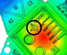
Figure 1. A screw boss. Images courtesy of RJG Inc.
Like many part inconsistencies, these unwanted features are rooted in product design. Since you inject the material through a gate, it must flow through the cavity and around various features, such as holes or bosses (Figure 1). If a knit line is present in a screw boss, the boss will likely crack when a screw is driven into it, leading to part inconsistencies.
For automotive parts, this results in parts that bump, squeak, or rattle. For electronics, the broken screw boss will not allow proper compression of a seal, damaging precious PCB (printed circuit board) with water. For plumbing parts, if these occur in an O-ring groove, there is a possibility that there will be a weeping of fluid, causing a slow drip. In the pipe fitting industry, if they do not manage this well, a fitting will not pass burst or crush testing, yielding product field failures.


Think of this like water flowing down a river with a rock protruding through the surface. Once the water hits the rock, the flow must split, continue around, and converge on the opposite side. What we want to focus on is converging to determine if it’s a knit or meld line.
Meld Line
A meld line is defined as the remerging of two flow fronts after a feature within the part design splits the plastic flow. Visualize this as you’re getting onto the freeway after a long day at the office—we are all going the same direction and have to figure out how to get there without damage. Figure 2 shows how the flow front splits due to the rectangular core out and merges again on the opposite side. Since there is more space inside the mold cavity, the flow front continues onward, creating a new flow front.

Figure 2. Material flowing around and converging after the rectangular core out, continuing to flow and forming a meld line.
This joint is not as strong as an uninterrupted flow. Since the flow front can merge together and continue flowing through the cavity, there is a higher chance of being able to pressurize this area, therefore increasing its strength.
Knit Line
A knit line is when two flow fronts come together but, rather than merging, it’s like a head-on collision at a four-way stop. This isn’t pretty and will not end well (Figure 3).

Figure 3. Material flowing around standing core.
Once these two flow fronts meet, there is no more cavity geometry to flow through, thus making it challenging to pressurize this area of the part; subsequently, the result is even weaker than a meld line.
Material Selection
Certain materials are more forgiving with strength than others. Materials (HDPE, PP, POM) with streamlined structure (Figure 4) typically yield higher strengths because the polymer chains can more easily intermingle. The random structures that contain benzene rings found in other materials (PC, PMMA, ABS) reduce the ability for the polymer chains to merge smoothly. These benzene rings also increase the viscosity, reduce shrink rate, and increase strength except for knit and/or meld lines.
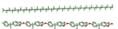
Figure 4. HDPE streamlined structure (top); PC with random structure (bottom).
Materials that have physical fillers like glass, carbon, metal flakes, etc. reduce the ability to influence the strength of a knit or meld line positively. This occurs for several reasons. First, the temperatures in which we process most thermoplastics (400 to 600o F) are drastically below the melting point of those types of fillers (glass is 2552 to 2912o F), if they even melt. In this situation, not only do we have a feature inside the cavity impeding the plastics flow, but we have a solid suspended in the flow front, further wreaking havoc. Therefore, we need to review the fiber orientation before the feature and how it differs after the feature (Figure 5).
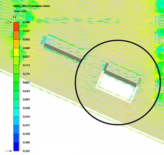
Figure 5. Fiber orientation pre- and post-core out.
The key to understanding changes in strength with a compromised part is understanding how test samples are broken down and how the data is collected.
The Izod Impact test, shown below in Figure 6, uses a weighted pendulum to strike a sample. Readouts are provided in the amount of energy required to break the sample, typically in ft-lb/in2. The more energy required to break the sample, the stronger the material is.
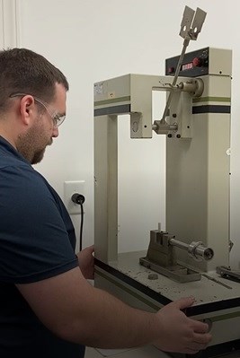
Figure 6. Izod impact test apparatus.
Another area that we need to review is the ASTM data from the notched and unnotched samples, shown below in Figure 7. Due to the elements that create the polymer, their arrangements and bonds determine how much strength is retained. A knit line is similar to that of a notch found in the ASTM sample.
Though a molded part with a knit line may not behave exactly like the test sample, the datasheet will show us how much strength could be potentially lost.
As an example, certain materials are so durable, the ASTM test cannot break the unnotched sample, but the value of the notched sample is tremendously low. One example of this is PC used in the medical industry (Chart 1).

Chart 1. Calibre™ MEGARAD™ 2081-15.
Other materials, like PP shown below in Chart 2, are breakable at the ASTM test method when both notched and unnotched.

Chart 2. Gapex® HP RPP20EU98HB.
Neither of these materials is terrible, but we must understand their limitations and how to accommodate the design to achieve the desired objective properly.
What we look at for indications of strength is the falloff between the unnotched and notched sample. This can help us understand the potential weakness of a knit line compared to an uninterrupted flow of plastic.

Figure 7. ASTM test samples.
Mold Design
Where a knit or meld line will be within the part geometry is heavily influenced by the gate location. Through the use of flow simulations, we can predict where those may occur. However, gate locations may be selected based on part functionality, placing knit or meld lines in critical areas for proper functionality.
Processing
Improving the strength of knit or meld lines can be tremendously difficult with processing since there are so many factors that are already locked in, such as part geometry, gate location, flow length, and material. The best we can hope for is to pressurize the knit or meld line better through the combination of melt temperature, mold temperature, flow rates, and holding pressures.
The difference between a knit and meld line is significant, dramatically impacting the part’s structural integrity. Knit and Meld lines are inherent to plastic injection molding. Eliminating them is often difficult due to product requirements. However, with a collaborative effort between product designer, mold maker, and molder, success is certainly obtainable.
About the Author
Jeremy Williams has over 20 years of experience in the plastics industry serving the medical, automotive, furniture, and appliance industries. He previously worked as a Principal Engineer, taking projects from design concept to products. Jeremy earned his Master Molder II certification in 2011, became an RJG Certified Trainer in 2012, and started at RJG in 2015. In addition to his extensive manufacturing background, he holds degrees in plastics and business. Currently Jeremy is a Consultant/Trainer with TZERO®, contact him at TZEROCORE@RJGINC.COM


Related Content

Forces and Calculations Are Key to Sizing Core Pull Hydraulic Cylinders
To select the correct cylinder, consider both set and pull stroke positions and then calculate forces.
Read More
Machining Center Spindles: What You Need to Know
Why and how to research spindle technology before purchasing a machining center.
Read More
Advantages and Disadvantages of Copper and Graphite Electrodes
Both copper and graphite provide approximately the same end result, so it is important for a shop to consider the advantages and disadvantages of each material in order to discover what would work best in their shop floor environment.
Read More
The Benefits of Hand Scraping
Accuracy and flatness are two benefits of hand scraping that help improve machine loop stiffness, workpiece surface finish and component geometry.
Read MoreRead Next

5 Questions to Ask Before Instrumenting a Mold
Instrumenting an injection molding machine with sensors can be a daunting task. It is a huge investment, after all, so how do you ensure that it will pay off in the end? The key is knowing the right questions to ask before you even begin. Here are the 5 most important questions to ask in chronological order.
Read More
How to Use a Conformally Cooled Sprue Bushing to Reduce Cycle Time and Ease Cost Pressures
Use of a new conformally cooled sprue bushing helped solve Midwest Mold Services’ problem with a big sprue that was hard to cool and preventing faster ejection times.
Read More
Are You a Moldmaker Considering 3D Printing? Consider the 3D Printing Workshop at NPE2024
Presentations will cover 3D printing for mold tooling, material innovation, product development, bridge production and full-scale, high-volume additive manufacturing.
Read More