
Taper Angles and Wire EDM
Software can help compensate for excessive erosion during taper cutting with wire EDM.
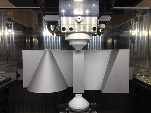
Software can compensate for correcting errors created by different cutting speeds between the top and bottom shapes in the cutting of four-axis parts, as shown. Images courtesy of Methods Machine Tools.
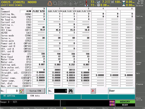
Figure 1 - Volumetric taper compensation can make adjustments on the EDM data screen using measurements from a test cut.
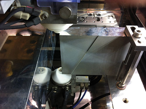
Figure 2 - This completed test cut shows program segments.


Wall straightness or angle accuracy often present a challenge to the machine operator when he or she is attempting to wire EDM taper angles. Several factors within the EDM process affect angle accuracy. These include, but are not limited to, temperature, machine design, material thickness and the machining technology required to cut the desired taper angle. Part geometry also affects angle accuracy. The shape of the part at the top of the workpiece and the corresponding shape at the bottom of the part have a great impact on how the correct angle is achieved with wire EDM.
To visualize this concept, think of a classic holiday ice skating performance. Skaters line up and start to rotate as one long line around an axis point in the middle of the rink. The skater on the end at the axis point turns very slowly in place, while the skaters on the outside end of the line need to skate very fast to keep up. What does all this have to do with cutting taper angles on a wire EDM? It comes down to the speed at which the upper guide travels around a shape verses the speed of the lower guide and the shape it is making. If the skates on the ice skaters were heated, the ice would melt faster under the slower spinning skater than under the faster traveling skaters.


Challenge
Imagine a cone-shaped part oriented with its tip at the top and cut vertically in half with wire EDM. From the side, the part appears wider on one end and narrower on the other end. When the operator programs cutting of the cone shape, he or she programs one end (top side) for U- and V-axis movement and the other end (bottom side) for X-and Y-axis movement. (Yes, this could have been accomplished by inserting a taper angle command instead of this four-axis programming, but to better explain this alternative feature for cutting accurate angles, we will discuss the use of a four-axis program.) As the wire is eroding the workpiece, slower motion keeps the wire in any given place longer than faster traverse speeds would. In other words, if the wire is moving slower, it is eroding more material than it would if it were moving fast, just like the slower moving ice skaters remove more ice than the faster moving skaters.
In EDMing the cone shape, the U and V axes will be travelling at a much slower speed to machine the upper (or smaller) radius than the X and Y axes will be travelling to machine the lower (or larger) radius. This means that more material will be machined away from the top profile than will be removed from the bottom. The radius actually will be smaller at the top than what was programmed, and the angle from top to bottom will now not be to program size.
Solution
Modern software offers a feature that allows the machine to offset the wire or change the taper angle on the wire. This compensates for the added wear on one end of the workpiece due to the differential between traverse speed in the X and Y axes and the U and V axes. The control tells the machine to change the programmed angle of the wire to “compensate” for the added erosion and then allows the operator to easily obtain the desired workpiece angle. With some simple data entry, the machine can do all the calculations needed to cut the angle correctly and accurately.
For example, when the moving distances of the wire along the top and bottom planes are different, the moving speed of the wire at each plane varies, as the U and V axes depart from the vertical location. During the programmed path, an over-/under-burn will occur, which results in a variance from desired feature sizes. Volumetric taper compensation can make an adjustment (based on variation from programmed sizes) on the EDM data screen (see Figure 1) using measurements from a test cut.
Taper compensation is activated by a simple software setting. The operator then selects the appropriate cutting technology, prepares a program for a test cut, performs a first cut, measures and records the measurements, and then enters the compensation value in the cutting technology register. For optimal accuracy, the measure points should be made at the beginning, mid-point and end of each programmed segment on both the top and bottom profiles (see Figure 2).
Taper cutting with wire EDM can be done accurately and efficiently as long as the proper systems and techniques are used. An advanced twin-servomotor tensioning system and control software that offers compensation for excessive erosion during taper cutting can help to achieve optimum cutting results.


Related Content

MoldMaking Technology's Most-Viewed Content 2022: Products
MMT shares the five top-viewed technologies, equipment and services of 2022 in each Engineer, Build, Maintain and Manage tenet based on Google Analytics.
Read More
Five-Axis Graphite Mill With Automation Debottlenecks Electrode Machining
Five-axis electrode cutting enabled Preferred Tool to EDM complex internal screw geometry on an insert that otherwise would have had to be outsourced.
Read More
Soft Wired: Cutting High Taper Angles with Wire EDM
Examine the wire’s properties to determine the right one for achieving the best cut.
Read More
How to Improve Your Current Efficiency Rate
An alternative approach to taking on more EDM-intensive work when technology and personnel investment is not an option.
Read MoreRead Next

Machine Capability, Service Go Hand-in-Hand
Although this Japanese builder has been offering equipment in North America for some time, it’s only recently benefitted from an extensive service and support network.
Read More
Reasons to Use Fiber Lasers for Mold Cleaning
Fiber lasers offer a simplicity, speed, control and portability, minimizing mold cleaning risks.
Read More
Are You a Moldmaker Considering 3D Printing? Consider the 3D Printing Workshop at NPE2024
Presentations will cover 3D printing for mold tooling, material innovation, product development, bridge production and full-scale, high-volume additive manufacturing.
Read More