


Figure 1. Maintain uniform wall thickness throughout the part. Poor design is shown on the left and a better design is shown on the right. Photo Credit: “Catoen, Injection Mold Design Handbook,” © Carl Hanser Verlag, Munich 2021
An injection-molded part should have a uniform wall thickness for even filling and cooling as much as possible. It is better to modify the geometry of a part to eliminate thick sections rather than design special cooling for the thick sections to prevent or only reduce unsightly sinks, voids and warpage. The poor design shown in Figure 1 (left) will never look like this in the finished molded part due to the changes in wall sections and sharp corners, and the plastic part will have sinks, warpage and a longer-than-necessary molding cycle. As a result, the molder will battle quality problems for the lifetime of the mold.
The better design, shown in Figure 1 (right), with cored-out sections, will be easier to mold, resulting in a part that is more consistent with a higher quality appearance. Decades ago, when plastics were being substituted for other materials, a designer’s biggest mistake was duplicating the existing nonplastic part rather than considering how to best make the part in plastic. However, once designers understood the advantages of using plastic for part consolidation, lightweighting, durability, shatter resistance, flexibility and many other features, plastics became the material of choice for part designers.


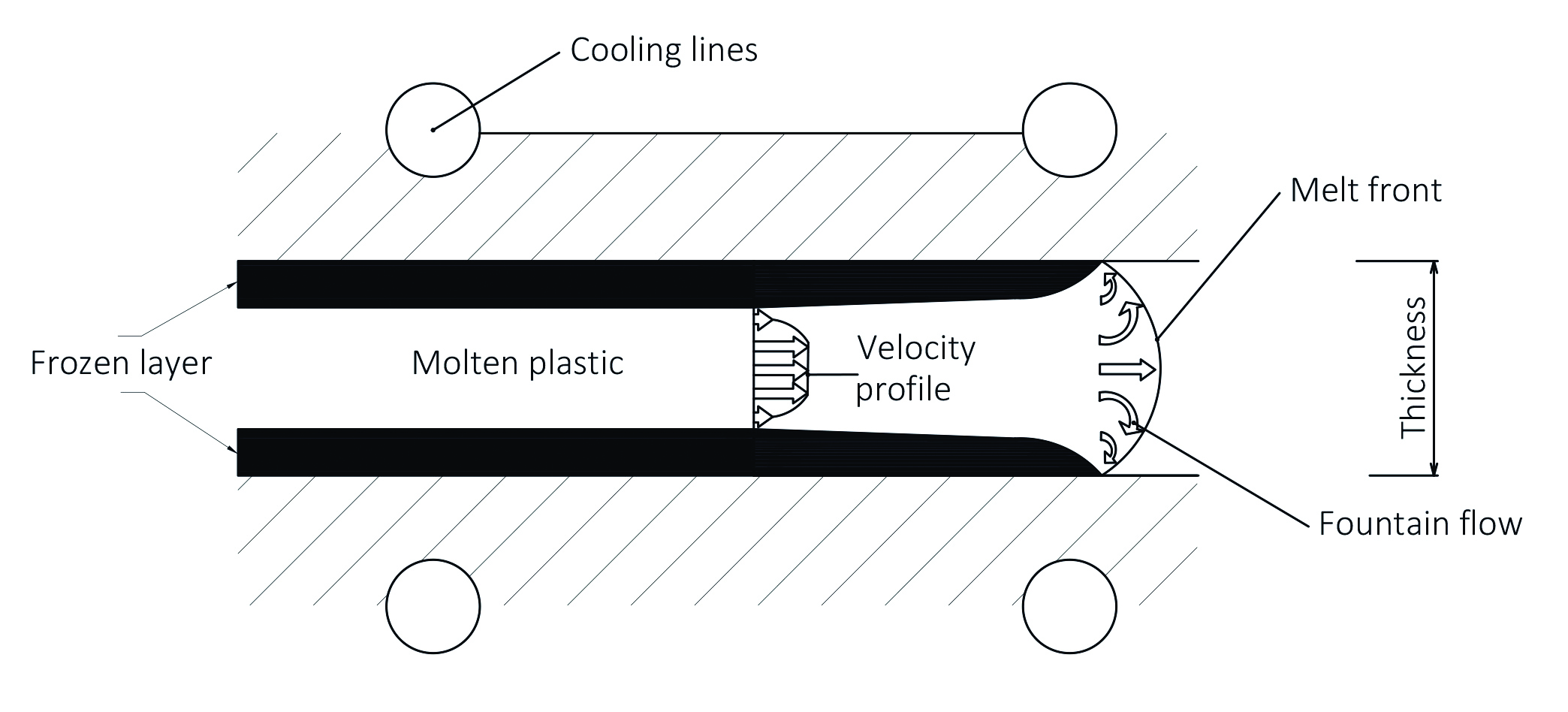
Figure 2. Fountain flow behavior of plastics. Photo Credit: “Catoen, Injection Mold Design Handbook,” © Carl Hanser Verlag, Munich 2021
Wall Section Transitions
Plastic flows along the path of least resistance with a fountain-like flow front (Figure 2). This must be taken into consideration when designing the part for moldability. There are a few good reasons for keeping the wall thickness as uniform as possible:
- The thicker the plastic wall section, the longer the cycle will be. This is because the thickest portion of the molded part will control the cycle time if the part is evenly cooled in the mold.
- The thicker sections will fill first and shrink more than a thinner section, which can cause sinks, voids, burn marks, shorts, and unexpected warpage in the cooled part.
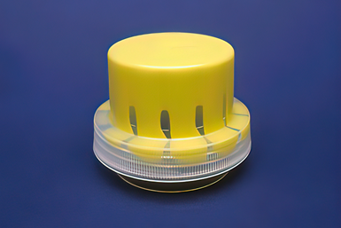
Figure 3. Plastic always flows along the path of least resistance. In other words, it flows further along thick sections, potentially causing quality issues. Photo Credit: “Catoen, Injection Mold Design Handbook,” © Carl Hanser Verlag, Munich 2021
Figure 3 illustrates how parts with uneven wall thicknesses fill. The detergent cap has facets around its circumference, which cause thick sections in the part. The cap was partially filled with clear resin and then finished filling with yellow-colored resin. As can be seen, the plastic in the thickest areas flows more easily and progresses further than in the thinner areas.
This geometry caused localized weld lines (points where two flow fronts come together) and a non-round thread profile. The mold was modified to reduce the facets, and the problem was resolved.
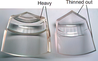
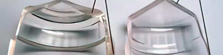
Figure 4. Sections through an injection-molded tumbler. The original design, on the left, had many sink, cycle time and surface finish issues due to the large wall thickness variations. The modified design on the right has reduced the wall variations. The molding issues were eliminated with this revised design. Photo Credit: “Catoen, Injection Mold Design Handbook,” © Carl Hanser Verlag, Munich 2021
Figure 4 shows cut sections through a molded tumbler. On the left is the original part. Note that the plastic flows from thin to thick to thin to thick and finally to thin. This makes the part very difficult to mold. On the right is the redesigned part. Modifying the core to flow from thick to thin reduced the part weight by 20% and, at the same time, decreased the cycle time by more than 30%. Finally, it eliminated many molded defects caused by the thick-to-thin transitions.
As a general rule, a plastic part should be thickest near the gate and thinnest at its furthest point from the gate. The transition from the thickest section at the gate to the thinnest at the end of flow should be as gradual as possible. However, sometimes differing wall sections cannot be avoided. If differing wall sections are required, it is advisable to make the transition between thicknesses as smooth as possible and to avoid any sudden changes in wall sections, which can cause high stresses in the cooled part and very noticeable sinks or voids (see Figure 5 for advice on wall section transitions).
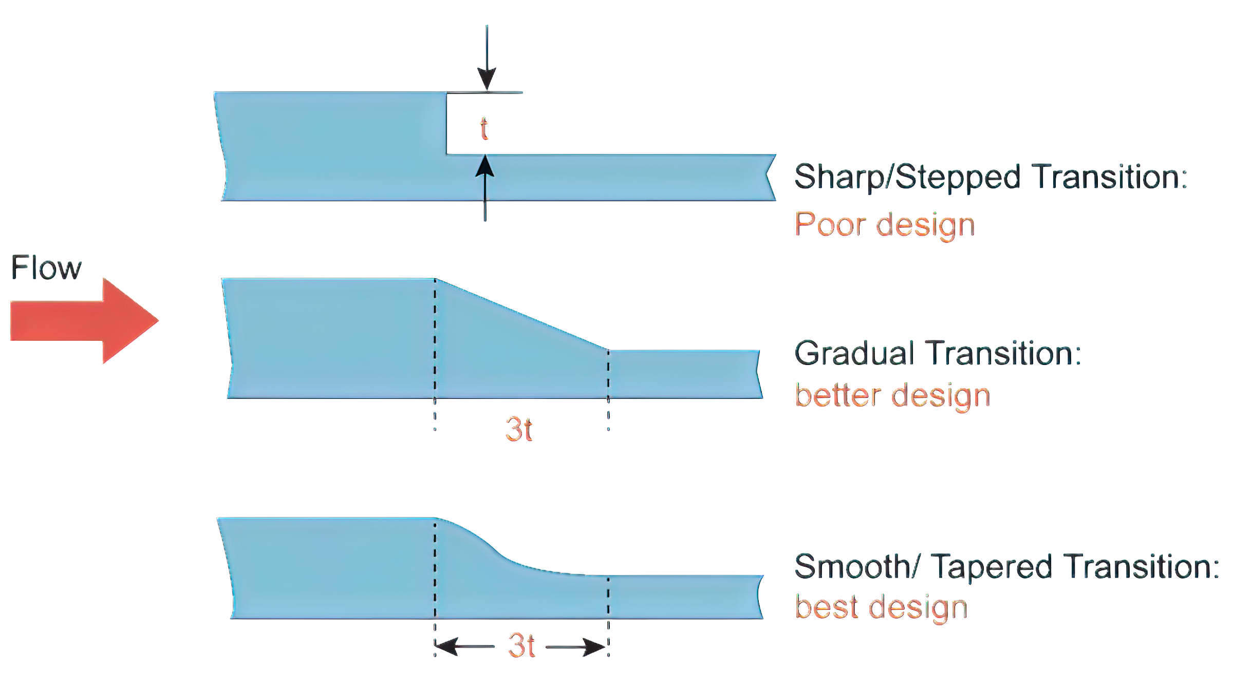
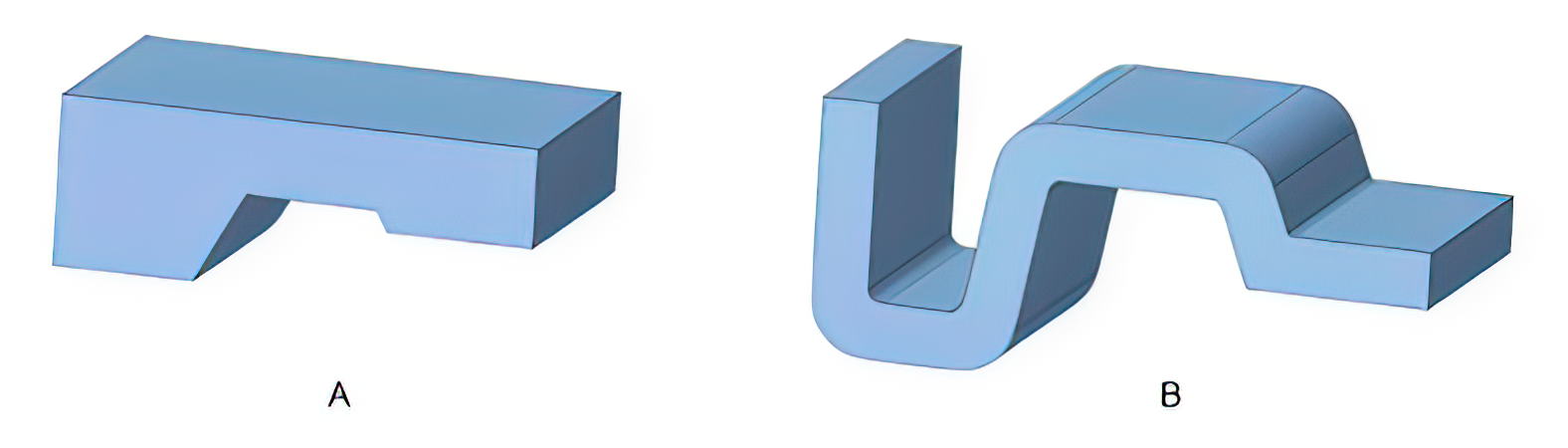
Figure 5. Poor wall thickness transition (top), better design (middle) and preferred design (bottom). Photo credit: “Molding Simulation: Theory and Practice,” M. Wang, R. Chang, C. Hsu. Hanser Publishing, 2018
Corners and Fillets
Sharp corners or fillets cause localized thicker sections and should be avoided in plastic part design, if possible. Sharp corners can cause stress fractures in the part, are difficult to fill completely, increase the pressures required to fill the part and make mold manufacture more complex. As the radius or fillet gets larger, the stress concentration produced decreases rapidly.
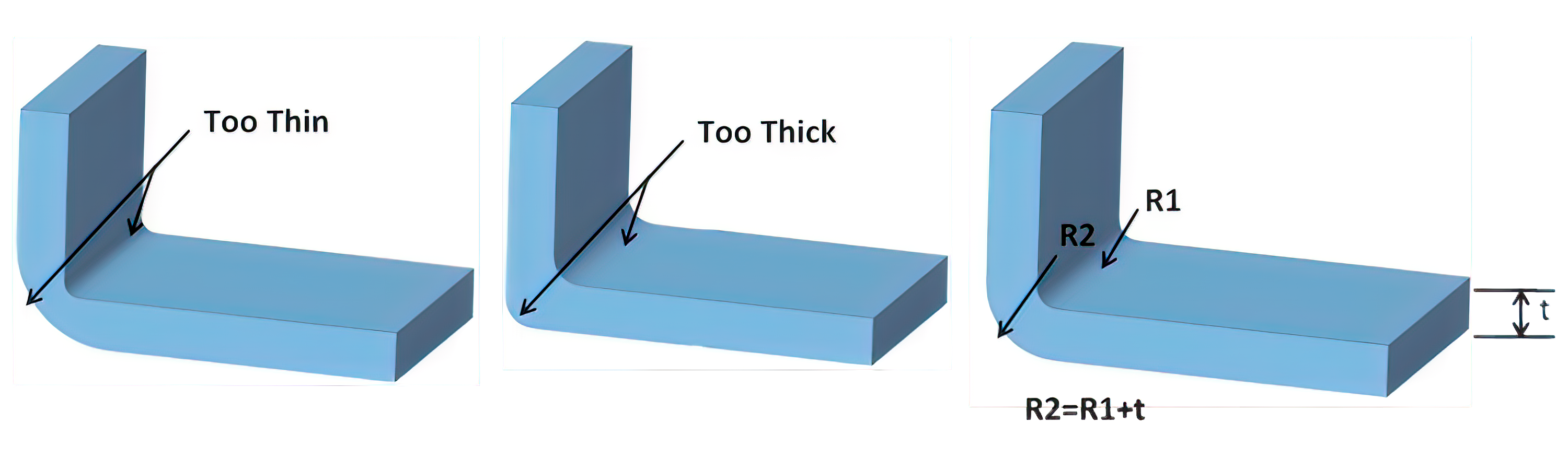
Figure 6. The outside radius is too large, causing a thin section (left). The outside radius is too small, causing a thick section (middle). The inside radius and outside radius match (right). Photo credit: “Molding Simulation: Theory and Practice,” M. Wang, R. Chang, C. Hsu. Hanser Publishing, 2018.
The corner radii should match to produce an even wall section throughout the corner, as shown in Figure 6 (right). If the outside radius is too large (left), then the filling can be restricted and the part weakened. If the outside radius is too small (middle), then the part becomes too thick in this region, causing localized racetrack filling of the part and wasted plastic in the part.
As a rule of thumb, any external corner or radius should be a minimum of 150% of the wall thickness, and the corresponding internal radius should be at least 50% of the wall thickness.
Ribs and Bosses
Ribs and bosses are commonly used in plastic parts for reinforcement and assembly. While needed for the physical strength of the molded part, they can cause molding defects such as sinks, voids, shorts and trapped air if incorrectly specified.
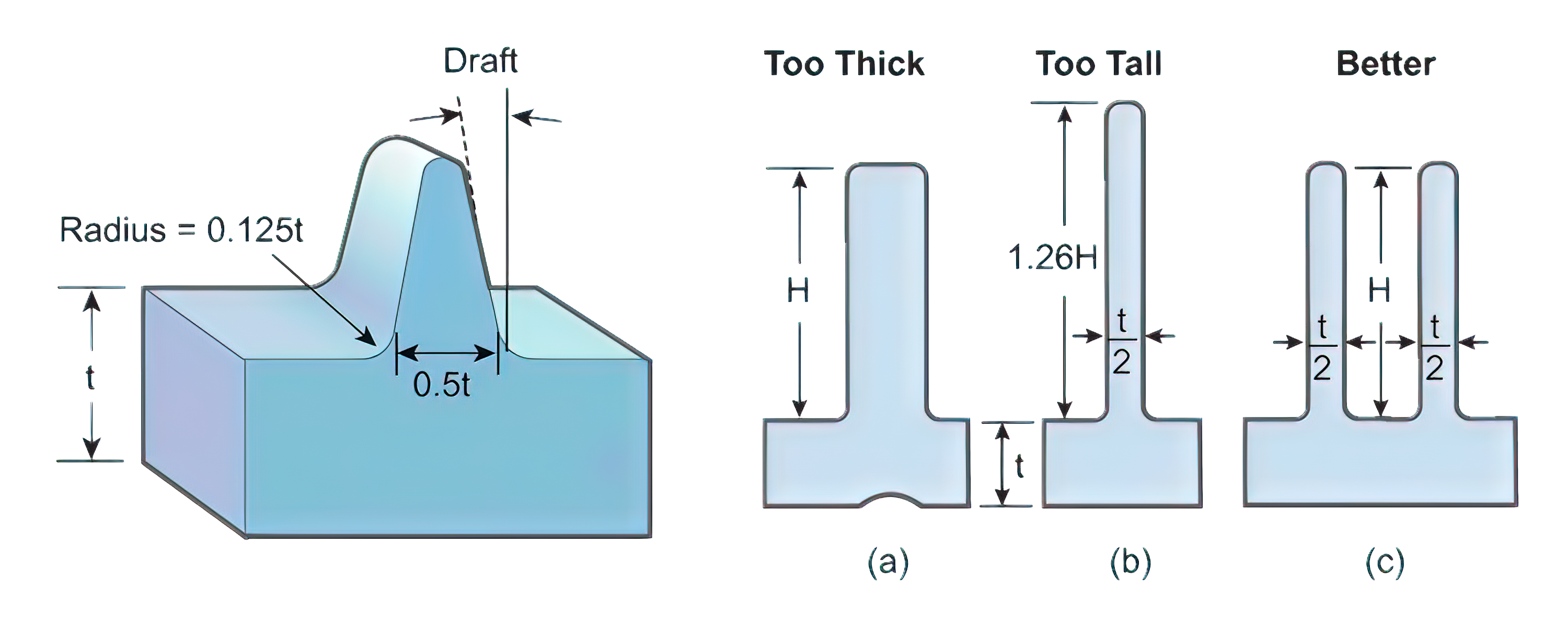
Figure 7. Recommended dimensions for a rib in a molded part. H < 3t. Photo Credit: “Molding Simulation: Theory and Practice,” M. Wang, R. Chang, C. Hsu. Hanser Publishing, 2018
To prevent defects in the molded part, the guidelines below and in Figures 7 and 8 should be followed when feasible:
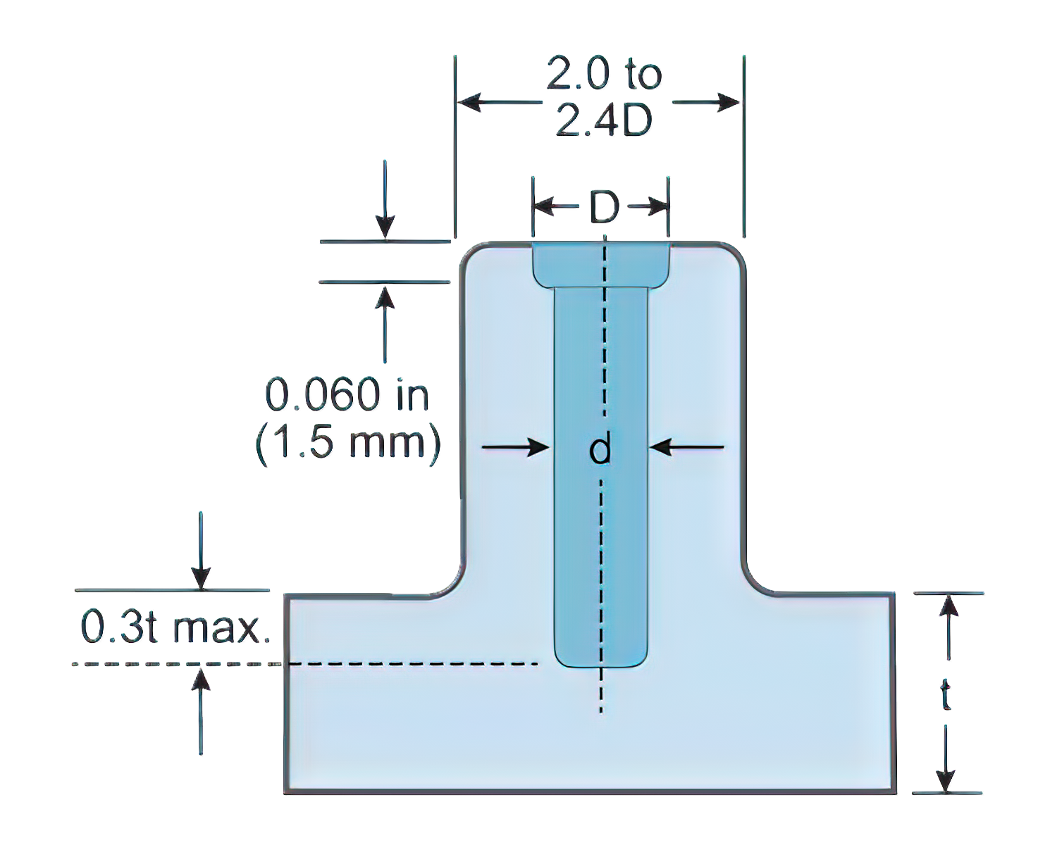
Figure 8. Recommended dimensions for a boss in a molded part. Rib t > 3d. Photo Credit: “Molding Simulation: Theory and Practice,” M. Wang, R. Chang, C. Hsu. Hanser Publishing, 2018
- The rib height should be less than 3 times the part wall thickness. If greater than this, the rib should be vented.
- The draft on all ribs and bosses should be 0.5° or more per side to allow for ejection.
- The span between two ribs should be greater than 2 times the wall thickness at the rib base.
A good way to hide the location of a rib or a boss is to put a transition where it intersects the main wall section so that the sink is not noticeable (Figure 9).
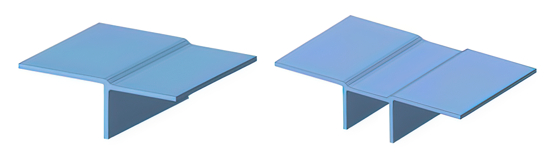
Figure 9. Hiding the location of a rib or boss in a transition prevents unsightly sinks. Photo Credit: “Molding Simulation: Theory and Practice,” M. Wang, R. Chang, C. Hsu. Hanser Publishing, 2018
Lip and Rim Designs
Figure 10-A shows a full round rim design frequently specified on plastic parts. The large bead rim shape is not recommended as the rim is typically at the end of the flow path and such a rim will be difficult to fill and pack. The result is either a void, usually with amorphous plastics, such as PS, which freeze rapidly on the surface (Figure 10-A1), or a sink, usually with crystalline plastics, which freeze slower and pull the still-soft plastic skin toward the center, as shown, exaggerated, in Figure 10-A2.
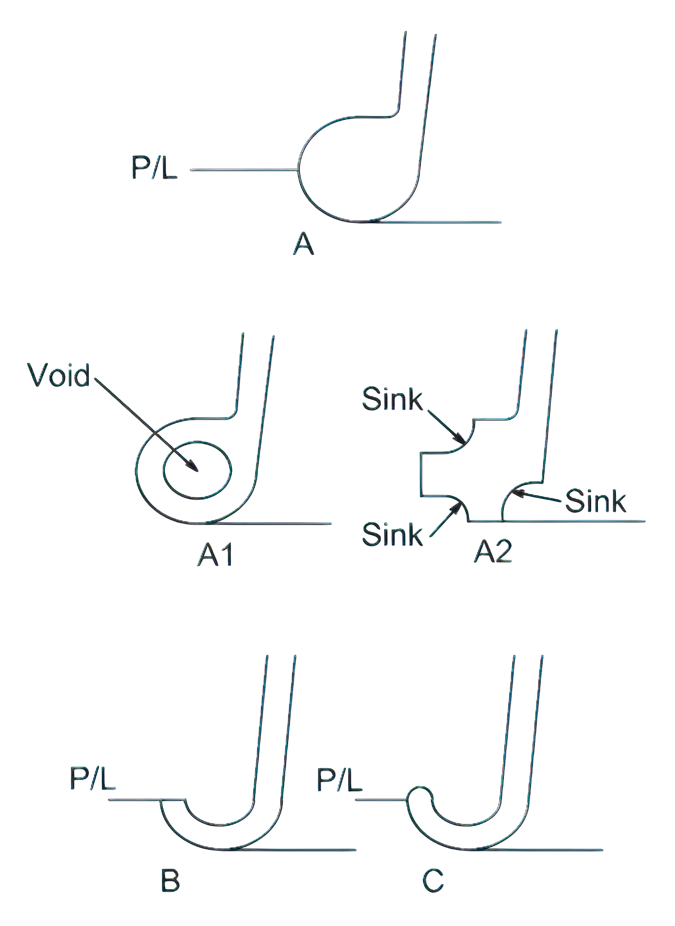
Figure 10. The large bead rim at the end of flow (A) can produce voids and sinks. Modifying the design shown in B or C will avoid these molding problems. P/L = parting line. Photo Credit: “Catoen, Injection Mold Design Handbook,” © Carl Hanser Verlag, Munich 2021
In addition, the bead rim dimension will be difficult to control dimensionally and cause sealing or fit issues with the mating component. A better plastic part design would avoid such large cross-sections at the end of any flow path.
The design shown in Figure 10-B or C will not have the risk of sinks or voids and will be dimensionally stable. An additional benefit of design B or C is that these options will use less plastic and permit faster cycles, resulting in lower product costs.
Check Your Design Using a CAE Flow Simulation Software
Once you have revised your part and mold design to reduce the thick sections and improve the transitions in the part, it is very useful (even essential) to simulate the filling of the part using a flow modeling software. These programs are extremely helpful for ensuring that the resulting molded part will fill in the way you anticipated.
The program will be able to identify any potential problems, such as filling issues, hot spots, warpage, voids and other molding issues in the injection-molded part. Once you have completed an acceptable molding simulation and have an approved part drawing from the customer, the detailed mold design process can begin.


Related Content

How to Select a Mold Temperature Controller
White paper shares how cooling channel analysis, which collects maximum pressure drop, total flow rate and heat dissipation, eases the performance evaluation of mold temperature controllers.
Read More
Mold Design Review: The Complete Checklist
Gerardo (Jerry) Miranda III, former global tooling manager for Oakley sunglasses, reshares his complete mold design checklist, an essential part of the product time and cost-to-market process.
Read More
MoldMaking Technology's Most-Viewed Content 2022: Products
MMT shares the five top-viewed technologies, equipment and services of 2022 in each Engineer, Build, Maintain and Manage tenet based on Google Analytics.
Read More
The In's and Out's of Ballbar Calibration
This machine tool diagnostic device allows the detection of errors noticeable only while machine tools are in motion.
Read MoreRead Next

Mold Design Review: The Complete Checklist
Gerardo (Jerry) Miranda III, former global tooling manager for Oakley sunglasses, reshares his complete mold design checklist, an essential part of the product time and cost-to-market process.
Read More
It Starts With the Part: A Plastic Part Checklist Ensures Good Mold Design
All successful mold build projects start with examining the part to be molded to ensure it is moldable and will meet the customers' production objectives.
Read More
MMT Chats: Giving Back by Answering the Moldmaking Education Need
MoldMaking Technology Editorial Director Christina Fuges checks in with Bruce Cateon, an executive advisor at OASIC Consulting. Bruce started out in moldmaking, eventually becoming an industry consultant and taking time to work on his passion project the “Injection Mold Design Handbook” as a way of giving back to the industry that has given him so much. This episode is brought to you by ISCAR with New Ideas for Machining Intelligently.
Read More