


Molders, mold builders and repair technicians are regularly challenged with manifold systems that leak plastic. Also referred to as encapsulation, flooding or cocooning, this costly repair is a main source of anxiety during manifold maintenance.
Let’s take a look at what can happen when molders, mold builders and repair technicians do not understand manifold and component expansion that occurs when they shoot a manifold or repair one in the press, or on a bench.


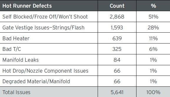
A survey of 12 companies over a three-year period reveals the most common manifold issues that create part defects or unscheduled mold stops. The data tracked 5,641 less costly manifold issues that plague hot runner systems. Although encapsulation places fifth on the list after freezing off, long gates and bad thermocouples and heaters, they are recalled more vividly as they are time consuming and expensive to repair. For example, many man hours are required to melt and chip off the plastic from around the wiring and other components when the repair is done in-house, but a shop can save roughly 75% of the heaters and thermocouples. If a shop opts to send the manifold to a supplier that uses a fluidized sand bath system to clean a hot runner system, the manifold will get very clean quickly, but the heaters and thermocouples will be ruined.
Soak time. Most experienced molders know that failing to soak manifolds for a specified time after they reach operating temperature is the most common cause of manifold leaks. Without this soak time, many manifolds will not have adequate pressure exerted around the seal point between the manifold and the nozzle. However, many processors believe this is “overly cautious” since they shoot some molds immediately after reaching process temperature with no issues. They believe that if it works on one system, it should work for all systems. However, be sure to consider these influencing factors: resin and additive type and the nozzle’s connection to the manifold.
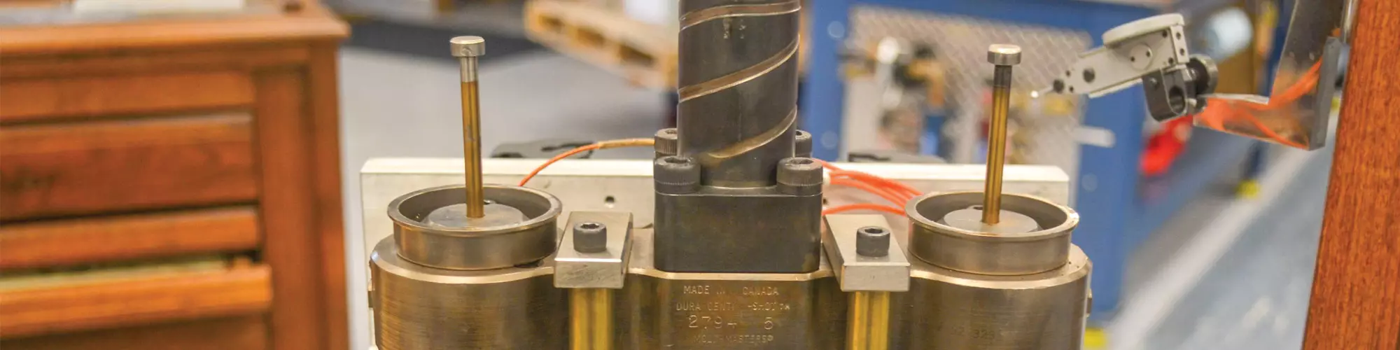
To demonstrate the expansion of soak time on several manifold components, we built a small prototype system with a heated sprue, two nozzles, two expansion spacers and two valve pins. This mold showed that just because a thermocouple says that a specific temperature has been reached, it does not mean that the steel has fully expanded, providing a good seal and proper component alignment.
Coefficient of expansion. Different materials have different coefficients of thermal expansion. The expansion rate of steel, which is an isotropic material (meaning heat produces expansion equally in two directions) is influenced by the amount of carbon, nickel, chromium and other alloys. This mix makes it important to know the exact type of steel components in your system, so you can use the correct coefficient in online steel expansion calculators.
Critical measurements. Although the test rig image shows expansion in the “A” dimension, which is the total height of the manifold/nozzle/expansion spacer stack, expansion in the other dimensions (B and C) can also cause leaks, bad parts and component damage.
For the “A” dimension, focus on the increase in the manifold/nozzle/expansion spacer total stack height thickness as this forms the compression necessary to seal the nozzle to the manifold when the expansion spacer is compressed against a retaining or back plate, and the nozzle skirt is against the face of a bore. If there is not sufficient growth, it will leak. Conversely, too much heat (growth) can cause broken bolts, cracked nozzles and hobbed counterbores and plates.
The valve pin growth at the “B” dimension is critical as it determines the amount of preload being exerted on the gate inserts. Too much growth in this location due to excessive heat or an incorrect valve pin length can crack the thin land area around gate inserts. If there is not sufficient growth, the valve pin taper will not fully contact the gate insert, resulting in inadequate cooling and a long gate vestige.
The “C” dimension is the centerline distance from valve pin to valve pin and/or nozzle to nozzle. The growth in this location can be significant, especially in 24-inch or longer manifold systems.
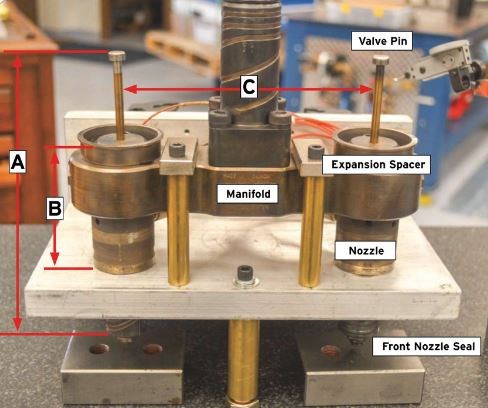
Test rig for indicating critical dimensions.
Measuring the model. The height of the three-piece stack (A) is 3.250 inches at room temperature, and with the manifold and nozzle heaters set at 400°F it takes only three minutes to reach the set temperature. However, the manifold and heaters only expanded 0.002 inch, which does not create a tight seal.
After 15 minutes, expansion increased another 0.003 inch. Then after soaking for a half-hour, the manifold and nozzle heaters reached full expansion height of 3.257 inches, or 0.007 inch total expansion. Heating for another 15 minutes produced no additional expansion. So even with a small manifold, it takes a half-hour of soak time to see full expansion. Enclosing this system might reduce the time, but not significantly.
Valve pin growth (B) expanded from a cold height of 6.688 to 6.703 inches, or 0.015 inch after a half-hour. This amount of expansion requires accurate component stacking to obtain the proper preload at the taper (usually around 0.002 to 0.005 inch) on the gate area and not break through. It is never a good idea to mix up valve pins as they might be matched to their location.
Another critical area is the centerline distance between the nozzles and valve pins (C). When heated for a half-hour at 400°F, the distance between the nozzles expands 0.013 inch, which means each nozzle moved off-center 0.006 inch.
Nozzle centerline expansion (C) is the culprit of damaged front nozzle seals during in-press work when a technician removes the gate insert plate to access to the nozzles. The fit between the front nozzle seal and the matching bore in the gate inserts is tight at 0.0002 to 0.0005 inch to not leak plastic.
If a technician re-installs a gate insert plate to a manifold plate in the press, or on the bench, where the nozzles remain hot and expanded and the gate insert plate is significantly cool (decreasing the centerline distance), the seals will misalign to the bore and significantly “scuff” during assembly. This result will cause plastic leaks that migrate back through the whole system over time and possibly go unnoticed until the manifold is pulled for preventive maintenance or other work. It is critical to cool systems and ensure plates are only a few degrees apart before working manifolds. Steel calculators are very useful at this point.
Calculate to be safe. To compare several steel expansion calculators with my actual values, I punched in the numbers generated by the test rig using 6.5 inches as the coefficient of expansion. To my surprise, the calculated values produced by the chart at 400°F were within 0.001-inch of my actual values.
Let’s review expansion numbers for a typically large manifold with outboard nozzle centerlines 24 inches apart. This length and 400°F processing temperature produces a 0.054-inch expansion from the center of the outboard nozzles, or 0.027-inch from the centerline of the manifold to the outboard positions.
Since the 24-inch nozzle centerline distance expanded to 24.054 inches at 400°F and the gate insert centerline shrank to 24.046 inches after being cooled to only 350°F, the mismatch between the outboard hot nozzle and the outboard cooled gate insert is a 0.008/2 or 0.004-inch mismatch between the outboard nozzle seal and the gate insert. This is more than enough to damage the nozzle seal during re-assembly of the two plates. The lesson here is to make sure the plates are at room temperature when working on them or use a calculator to determine a safe temperature difference between the components.
Knowledge Is Power
Molders, mold builders and repair technicians must fully understand thermal expansion and the criticality of correct thermocouple type and placement to reading the actual temperature of the components, which ensures proper manifold and nozzle soak time after reaching processing temperature.
Understanding the order in which components heat up is just as important as understanding the expansion required to get critical seals that prevent leaks and ensure proper alignment. Therefore, heat the manifold first during start-up to fully expand it before the nozzles heat up, and apply pressure to the seal area. If technicians perform these steps in reverse, an expanded nozzle can scuff or drag across the manifold and cause leaks.
Click here for a sample online expansion calculator.
For More Information
MoldTrax / moldtrax.com / 419-281-0790 / steve@moldtrax.com
About the Contributor
Steve Johnson
Steve Johnson is president of MoldTrax, which provides specialized course work, hands-on bench training, maintenance software, maintenance products, toolroom design and maintenance efficiency auditing.


Related Content

How to Solve Hot Runner Challenges When Molding with Bioresins
A review of the considerations and adaptations required to design hot runners and implement highly productive injection molding operations.
Read More
How to Use Hot Runner Balance in Mold Qualification
If you are interested in the impact of system and hot runner balance on part quality, the causes of unbalanced hot runner systems and short shot parts, the procedure for measuring system balance and the impact of application specifics on system and hot runner balance expectations, then tune into this on-demand webinar.
Read More
Hands-on Workshop Teaches Mold Maintenance Process
Intensive workshop teaches the process of mold maintenance to help put an end to the firefighting culture of many toolrooms.
Read More
Revisiting Some Hot Runner Fundamentals
What exactly does a hot runner do? If you’ve been in the injection molding industry for any length of time, you might think the answer is obvious, but it is not.
Read MoreRead Next

Best Practices in Mold Maintenance and Repair
More complex molds have created a need for more complex maintenance and repair operations.
Read More
“Riding” the Mold Maintenance Highway!
This year’s amerimold saw the debut of an aisle devoted to mold maintenance equipment and products, which was organized by Progressive Components.
Read More
Overcoming Pain Points in Moldmaking with AI
Shops that embrace AI as a tool, not a threat, can enhance efficiency, preserve expertise, and attract tech-savvy talent.
Read More