
Paperless Mold Design and Manufacture
The European Union, a software supplier and several moldmakers teamed up to determine what moldmakers need most when designing molds - and the best way to fulfill those needs.


Automatic core and cavity creation from a part.
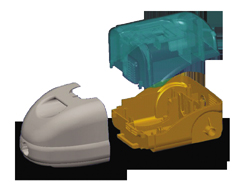
Splitting of a part ready for production.
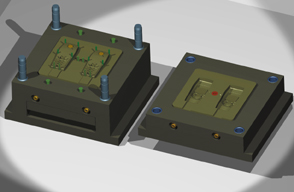
Automatic mold design.
Between 1998 and 2000, the European Union - through its national governments via the EUREKA scheme - a pan-European network for encouraging near market, collaborative R&D projects which lead to the development of advanced products, processes or services that involves organizations from 24 European countries and the Commission of the European Union - sponsored a major research and development project into paperless mold design and manufacture. This paper describes the work undertaken in the project and the results generated.
The Project
The project aims were as follows:


- To research into the complete life cycle of the design and manufacture of a mold tool in order to find and alleviate bottlenecks in these processes.
- To enable molds to be manufactured directly - and semi-automatically - from the master CAD model.
- To add information necessary for manufacture to the CAD model.
- To generate any necessary paperwork (e.g., setup sheets) automatically from the master CAD model.
- To enable all interested parties within a company to be able to access the information they need from the master CAD model.
In other words, the project aimed to use the master CAD model as a central reference source for all work and remove the need (as much as possible) for paper documents that describe aspects of this model. It aimed to enhance the content of this model, and to streamline the processes involved in building and maintaining the model and all downstream processes derived from the model.
The Consortium
The consortium consisted of:
- A CAD/CAM software vendor.
- Three moldmakers - one specializing in small high-precision molds such as mobile phones and two specializing in large molds, such as automotive instrument panels and fenders.
- An advisory panel of UK moldmakers, including support from the UK mold and die trade association (GTMA) and British Plastics Association (BPA).
- An advisory panel of Spanish moldmakers.
The Mold Design and Manufacture Life Cycle
The life cycle of a mold was broken down into the following stages.
Stage 1: Estimating and Quoting
The main requirement thrown up by the research into this stage of the life cycle was that managers wanted a good viewing and estimating tool that was oriented directly at moldmakers.
- Some moldmakers were already using CAD viewers but these were generally facetted viewers. This type of viewer was OK for viewing and sectioning, but had problems when measuring radii, diameters, etc. because such values had to be approximated from a facetted model of the true geometry.
- They wanted "simple" drafting functionality in this tool, such as the ability to add a few dimensions for major lengths, and the ability to generate full-size plots.
- They wanted functionality specific to toolmaking, rather than for general purpose CAD model viewing, e.g., tools for finding and visualizing undercuts, tools for measuring draft-angle and wall-thickness.
Stage 2: Importing the Product Model and Regenerating a Good Solid Model
The research revealed the following main issues.
- Toolmakers need to read data from many sources.
- Some sources are only encountered infrequently.
- Most modelers are poor at data exchange. As a result, an imported model often has missing surfaces, badly trimmed surfaces and requires a great deal of work to rebuild a good quality solid model.
- The fixing stage takes several days.
- Most modelers are poor at complex surface modeling (surface fitting, stitching, etc.).
- Most modelers cannot work well with imported data from modelers working at coarser tolerances, which means you can't import the data; you can't stitch the imported surfaces into a solid and you can't work robustly with the solid once made.
Stage 3: Completion of the Product Model
The next stage in the life cycle was shown to be completion of the product model. In some cases, the model was deliberately incomplete, and the product designer (having created a model that is sufficiently complete to agree styling and fit issues) had left some detailed modeling (e.g., filleting) to the moldmaker to reduce costs. For automotive work, it is common for moldmakers to receive only the A (outside) surfaces, and for them to be expected to generate the internal surfaces themselves - as an offset of the outer surfaces by wall-thickness.
In cases where the moldmaker does receive a complete solid model, it is necessary to split the model into two groups of surfaces - those for the core and those for the cavity of the mold. Even if the product model was notionally complete when received, extra work was generally required to change draft angles, wall thicknesses, etc. to ensure the part could be successfully molded. The problems experienced by moldmakers in this stage typically included:
- Most modelers are poor at offsetting, so generating the B surfaces from the A surfaces could be problematic.
- Most modelers have no specific functionality to separate core and cavity surfaces if a solid model is received. This work can be very time consuming.
- Most modelers have no specific functionality to measure draft angles and wall thicknesses.
- Most modelers have no specific functionality for adding extra draft (to facilitate extraction from the mold).
Stage 4: Generation of the Tooling Model
Once the product model is complete and has been modified to ensure moldability, the next stage is to generate the model of the tooling. This involves two stages - generating the model of the die blocks (which incorporate the mold core and cavity) and then generating the rest of the mold assembly (the whole mold base and other ancillary components). The problems typically experienced by moldmakers were:
- Most modelers have to generate parting surfaces piece by piece and fill in gaps and trim back intersections. This can be very time consuming.
- Catalogs of standard mold components are required.
- Most toolmakers wanted to build the tooling assembly model from solids, and saw a solid modeler as the appropriate CAD tool for this. However, the core, cavity and slides require surface modeling tools, and most toolmakers felt that there were no suitable tools that combined the best of solid and surface modeling. Toolmakers using solid modelers for the tool assembly typically had problems building solids from the imported surfaces they received by IGES, and this could either be very time consuming, or a complete block on production of the tooling via solid modeling.
Stage 5: Preparation for Manufacture
Once the components of the tool have been fully modeled, there are still some steps to be taken before manufacture can proceed. For milled parts, the machinist must decide on the appropriate cutter size. For areas that are difficult or impossible to mill (e.g., sharp internal corners, narrow slots, etc.) electrodes will be required to spark the area instead. The companies surveyed in the project had the following problems at this stage in the toolmaking process.
- It was not easy to see by eye what is the best size cutter to use for milling each area.
- Electrode modeling caused major time delays. Typically, the electrode model is the inverse of an area of the component model, created by copying that geometry and trimming it back. The original area of the main model needs to be filled in, so that the sparked area is not milled. The copied surfaces - representing the electrode - have to be extended slightly around the edge of the electrode to allow for over-burn, and then extrusion surfaces are added to form the body of the electrode. The following problem areas were highlighted.
- Separating electrode geometry requires very good surface trimming - this often needs to be done surface-by-surface - which takes a long time.
- Extending surfaces for over-burn also is laborious - usually surface-by-surface.
- Setup sheets are required to tell the EDM operator where each electrode must be positioned. These were a major cause of error and tedium.
Stage 6: Generation of Cutter Paths for Manufacture
At the time of the research, the generation of 3-D milling cutterpaths from the master CAD model was already fairly automatic. The problem areas were seen as the 2-D machining steps, as the common practice was to use a separate 2-D machining software package to generate the 2-D machining paths (for drilling, etc.). Toolmakers were typically exporting 2-D DXF - which was the common input format used by such packages - then re-inputting extra data, such as hole depths, manually. This process was clearly error prone, time consuming and essentially unnecessary. Another problem was that the 2-D features then had to be removed from the model used for 3-D milling - to stop the milling cutter dipping into drilled holes.
The toolmakers wanted a system that integrated the 2-D and 3-D machining steps - working from a single master model.
Concurrent Engineering
In general, the toolmakers were expected to start the tooling design before the product design was finalized. Throughout all of the above stages, they received frequent changes to the product design as replacement IGES files. Generally, the whole model was received - not just the change. This meant that the toolmakers were always worried that they could miss a change and that this could result in major rework or the scrapping of a tool if the change was not discovered until a late stage. They wanted a means of telling with complete assurance what changes had taken place between each revision of a received product model.
The Project Results
The project has produced a CAD software package that is totally focussed on toolmaking, and uses a hybrid modeling approach to combine the best of solid and surface modeling. Rather than providing general purpose CAD tools, a large number of very specific tools are provided to support each stage of the toolmaking process. The CAD system builds a 3-D model that is very rich in manufacturing knowledge, and so is capable of use as the master source of manufacturing information throughout the company. It can be accessed through a toolmaking-oriented viewer - available free throughout an organization - and can be used to generate cutterpaths for both 3-D milling and 2-D drilling; to generate electrodes for EDM; and to generate all necessary setup sheets for manufacture. Where paper documents are still required, they are generated semi-automatically from the master model and are not necessary as input into subsequent processes (such as 2-D machining). The era of paperless mold design and manufacture has truly arrived.
Figure 1 summarizes the main results developed.
Figure 1
| Handling Quotations | Intelligent Automation | Mold Design Functionality |
|
|
|
|
| Data Exchange | Repair/Handling of Improted Data Electrode Modeling | Electrode Modeling |
|
|
|
|
| Handling Design Changes | Manufacture From Master CAD Model | Documentation From Master CAD Model |
|
|
|
|
Benefits to the Project Partners
One of the moldmaking partners in the project reports, "Working with the results of this project, we have, as a direct result, been able to instigate and adopt major changes and improvements to the quality, features, control and accuracy of CAD-based component and mold data. This has allowed rapid creation and analysis of complex tool surfaces from a variety of customer sources - plus the application of improved cutterpath facilities - to be produced promptly and effectively, thus significantly increasing the efficiency and output of both the CAD system and technical staff."
Another moldmaker in the project adds, "Since working on the project, we can now take in more complex models from our customers, create very complex tool surfaces and vastly improved cutterpaths and still develop the fully hardened production tools in less than eight weeks. Before the project, this type of tooling would have taken 10 to 12 weeks to produce. The software enhancements in the project allow us to split complex 3-D models for core and cavity far more easily and produce draft angles and split-lines more efficiently than before. The three-axis 3-D machining is now far easier to use, and the various new types of machining strategies have greatly improved the speed with which we machine hardened steel, copper and graphite on our dedicated high-speed mills. Another area that has been improved due to the project, which has always been a major pain and very time consuming, is the addition of automatically generated setup sheets. Without these, the CNC mill operators would have no idea as to datum points, types of cutters to use and program descriptions."


Related Content

How to Lower Cycle Times With the Right Tool Steel
Combining excellent mechanical properties, high wear resistance and high thermal conductivity in a specialty tool steel yields cycle time reduction.
Read More
Most-Viewed Content of 2022
The most popular MoldMaking Technology content according to analytics reports over the past 12 months.
Read More
Soft Wired: Cutting High Taper Angles with Wire EDM
Examine the wire’s properties to determine the right one for achieving the best cut.
Read More
Advancing the Mold With New Technologies
This roundup is full of products and services that help answer concerns and meet needs for the industry. Featured in this roundup are hot runners, mold components, mold materials and more.
Read MoreRead Next

How to Use Continuing Education to Remain Competitive in Moldmaking
Continued training helps moldmakers make tooling decisions and properly use the latest cutting tool to efficiently machine high-quality molds.
Read More
Are You a Moldmaker Considering 3D Printing? Consider the 3D Printing Workshop at NPE2024
Presentations will cover 3D printing for mold tooling, material innovation, product development, bridge production and full-scale, high-volume additive manufacturing.
Read More
How to Use Strategic Planning Tools, Data to Manage the Human Side of Business
Q&A with Marion Wells, MMT EAB member and founder of Human Asset Management.
Read More