
Energy Savings in Multi-Cavity Molds
Simplifying maintenance and energy savings in the development of hot runner systems for multi-cavity molds for medical applications.
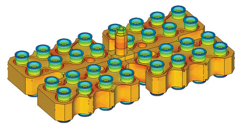
Thermal analysis of a 32-drop system.
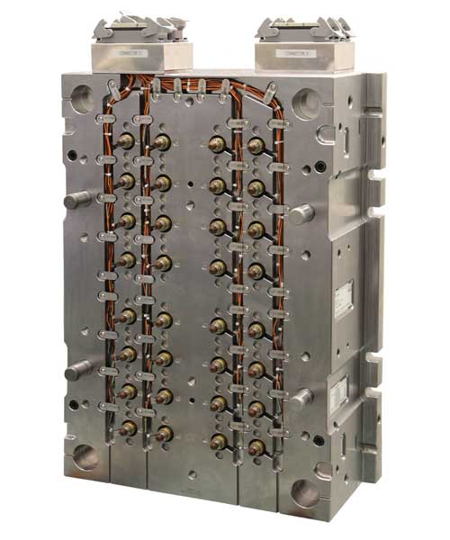
A 32-drop hot runner system for a PET blood tube mold.
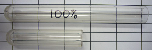
The interrupted shot obtained by loading a half dose demonstrated that melt feeding was not angled— so-called flute tip—but perpendicular to the longitudinal axis of the piece.
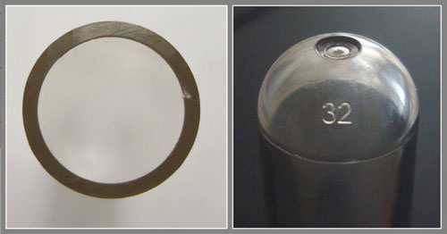
The section of the blood tube close to the spherical bottom highlights the optimal concentricity. Note thickness uniformity along the circumference. A close-up of the section near the gate shows the clean detachment of the pin from the plastic part and the absence of any sticking.


Constant research into thermoplastic materials, and offering improved performance as a consequence of heightened technical and economic needs, is leading to an ongoing evolution in molding. Research involves not only the process but also the machine and mold, which is in line with the growing aim to optimize all phases of the production process. The mold—considered the fundamental part of the system—is similarly developing at the same pace. Of particular interest is detailed research into energy savings, especially regarding the hot runner.
Energy Analysis
During some hot runner development R&D, finished parts were analyzed with the aid of specific software to simulate the system’s thermal, fluid dynamic and structural behavior during the design and engineering stage. System thermal homogeneity was also assessed during this analysis phase, estimating cycle energy consumption and checking any pressure drop and weight balancing of shots (see Figure 1).
In addition to the use of such instruments, it is essential to take advantage of those with hands-on experience and expertise, who pay close attention to simplifying system maintenance and energy-saving issues during any new hot runner product line development.
Keep in mind that energy savings is not limited solely to the system itself (thanks to reduced thermal dissipation between system and hot half), but also to reducing scrap during system restart.
Hot runners with excellent thermal stability combined with optimal canalization design are an ideal solution for many applications—including the medical, caps and closures, computer, electronics, housewares and cosmetics industries.
Another key aspect is the attention paid to designing the cooling system in the injection gate area, which facilitates restart (limiting production scrap as a result), improves the aesthetic quality of the injection gate and reduces cycle time.
To help achieve all of these benefits, look for a hot runner supplier that employs conformal cooling—inserts with cooling conduits close to the gate that are produced using selective laser melting technology (or some other form of additive manufacturing. See article in the Additive Manufacturing Supplement of MMT’s February 2012 issue). For example, in Figure 2 an engineering and production department manufactured the inserts and valve bushing with conformal cooling circuits.
Energy Savings Applied
A good example of an industry where a great deal of attention is paid to energy savings is the medical sector. It is also a sector where both in-depth experience and high technological performance are of paramount importance. These aspects are especially important when developing hot runner systems for blood tube applications.
Such applications require a detailed knowledge of mold/hot runner assembly in order to produce a product that complies with customer required strict tolerance levels. The application is critical since the material used is PET—with tube thickness averaging 1 mm and length 100 mm.
The combination of these factors requires a system with very advanced performance. Employing the aforementioned concepts ensures the mold/machine system yields a product complying with required specifications by processing the material inside the molding window recommended by the resin producer and reducing the initial cycle time by 25 percent.
In particular, there is a system involving the use of MTV39 and a specific valve guide to produce a PET tube (75-mm long with a weight of 3.6g, and 100-mm long with a weight of 4.9g). A 32-cavity hot half system produces the 75-mm one at a cycle time of 7.1 seconds.
This performance was achieved because of the integrated mold/injection machine system and close attention paid by experienced personnel during the design phase to ensure the required result fully met customer requirements—part weight homogeneity (+/- 1.5%), optimal concentricity, low energy consumption and perfect transparency.
To support the chosen technical solutions, a test was carried out to assess flow distribution. The interrupted shot obtained by loading a half dose demonstrated that melt feeding was not angled—so-called flute tip—but perpendicular to the longitudinal axis of the piece (see Figure 3).
Thanks to an accurate study of hot runner geometry, the melt flow in the cavity is almost axisymmetric with respect to the longitudinal axis of the piece. The absence of any preferential flow ensures the filling phase is regular; and, as a result leads to good external and internal cylindrical surface concentricity (see Figures 4 and 5).
Summary
When searching for solutions to save energy in your multi-cavity molds, work with technology suppliers who offer experience and expertise in the field of hot runner systems. The benefits of this relationship will be seen from the earliest stages of the project—beginning with product feasibility analysis, and criticality assessment based on application and material type— through to the proposition of improved solutions to achieve customer targets. This will improve operating efficiency; optimize the aesthetic and dimensional part requirements to ensure high repeatability; reduce cycle time; and, avoid any unnecessary waste of resources.


Related Content

Mold Builder Uses Metal 3D Printing to Bridge Medical Product Development to Production
Westminster Tool uses metal additive manufacturing for medical device OEM, taking lessons learned from R&D in the prototype mold phase to full-scale production molding in a fraction of the time.
Read More
Leading Mold Manufacturers Share Best Practices for Improving Efficiency
Precise Tooling Solutions, X-Cell Tool and Mold, M&M Tool and Mold, Ameritech Die & Mold, and Cavalier Tool & Manufacturing, sit down for a fast-paced Q&A focused on strategies for improving efficiencies across their operations.
Read More
Mold Builder Uses Counter-Intuitive Approach for Mold Challenges
Matrix Tool Inc. answers customers’ hard questions with creative solutions for cavity spacing, tool sizing, runner layout and melt delivery that reveal the benefits of running in a smaller press size at lower cavitation but higher yield.
Read More
U.S. Economy Indicates Prospects for Moldmakers
An examination of the U.S. economy suggests its resilience against a recession, yet a mixed outlook for moldmaking and plastics persists.
Read MoreRead Next

Selecting a Valve Gate Hot Runner
A look at valve gate plate actuation technology for consistent part filling, excellent gate quality and close nozzle spacing.
Read More
Reasons to Use Fiber Lasers for Mold Cleaning
Fiber lasers offer a simplicity, speed, control and portability, minimizing mold cleaning risks.
Read More
How to Use Continuing Education to Remain Competitive in Moldmaking
Continued training helps moldmakers make tooling decisions and properly use the latest cutting tool to efficiently machine high-quality molds.
Read More