Designing Injection Molds to Meet Validation Requirements Without Rework
Sponsored ContentIn injection molding, fixing molds that produce nonconforming parts is an expensive proposition. Here’s how to design and build tools that produce good parts from the start.
Share
Read Next

By Jeremy Williams
Consultant, Trainer, TZERO, RJG Inc.
Creating parts that are both in specification and dimensionally capable is not an easy task. Mold designers often struggle with qualifying parts for their customers before monetary transactions can occur. There are five areas of concern that should be addressed before the steel is cut: part design, tolerances and qualification, material selection, processing, and mold design. Below is a short journey through the design of a sample part to better understand what it takes to design and build a mold from the plastic’s point of view.
Part Design
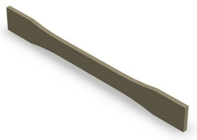
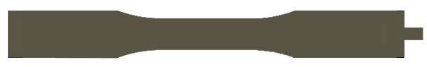
Complex shapes present a multitude of challenges for molders and mold makers alike. Here is a “simple” ASTM (American Society of Testing and Materials) Tensile Test Bar D638 Type III that will be used as an example while walking through the various aspects of mold design.
The tensile test bar has an overall length (OAL) of 9.700 in., width of 1.130 in., and thickness of 0.130 in. For the purposes of our exercise, we will focus on the OAL, since the design engineer views this to be the most critical aspect of part function.
Ball 1: the thicker wall section will slow down the heat transfer and helps with the ability to fill and pack minimizing shrink.
This simulation demonstrates shear imbalance in a multi-cavity H Type runner system. At the end you will see an imbalance in the fill between the outer four cavities vs. the inner four cavities.
Tolerances and Qualification
Often, the largest concern of mold designers or mold makers is to ensure the parts are within specification. However, there is more to the project than just being “in spec”. For products or parts to be validated, they typically must pass a capability study with a process capability index (Cpk) of 1.33 or 1.67. But what does this mean to the mold designer or mold maker?
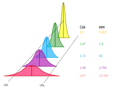
It means that the higher the Cpk requirement is, the closer to the nominal dimension the part must measure. An example is a nominal dimension of 9.700 in. with a ±0.005 in. tolerance and a Cpk of 1.33 (typical for automotive). In this case, the total range of samples must measure between 9.69875 in. and 9.70125 in. (±0.00125 in.). This means we can only use 50% of the total tolerance band for the parts to be capable. In contrast, if the Cpk requirement is 1.67 (typical for medical), all measured parts must measure no less than 9.69900 in. and no greater than 9.70100 in. (±0.001 in .), which is only 40% of the total tolerance.
Strike 1: Based on the part size, the total tolerance is 0.001% of the nominal dimension—this will be problematic because as parts get bigger, the tolerances also need to get bigger.
Material Selection
Materials with a semi-crystalline structure have very high shrink rates. For example, the shrink rate of a Polypropylene (PP) can be from 0.008 to 0.0035 in/in. We often hear the question, “Why does it matter what the range is? I’ll just select the middle, and it’ll be fine.” It matters because the molder will struggle to make parts with different lots of material that roll in through the door. So, let’s walk through a small example using the previously mentioned tensile test bar.
First, we need to take the nominal dimension and multiply the highest shrink rate (9.700 in. x 0.035 in/in = 0.3395 in.), then multiply the nominal dimension by the lowest shrink rate (9.700 in. x 0.008 in/in = 0.0776 in.). Now, we need to calculate the range of shrinkage the molder could expect to see if we used a single gate at one end of the part (0.3395 in. – 0.0776 in. = 0.2619 in.). Based on our previous calculations, the molder could see a range of shrinkage of 0.2619 in. If we compare this to the tolerance of ±0.005 in., the molder might be successful at molding good parts with a single lot of material, and that might even be a stretch.
This chart shows the variation that a molder will have to contend with throughout the life of the project.
In most cases, wide spec resins are used and will exhibit a variation in material viscosity of ±20%. With changes this large in material, we can expect part shrinkage to move as well and thus part dimensions will follow. One key factor to remember is that if the process doesn’t change, an increase in viscosity will yield smaller part dimensions due to longer polymer chains that are less compressible under the same pressure.
Strike 2: High shrink rate materials with large parts is a bad combination—bigger parts need larger tolerances.
Processing
In this case, the dimension that is the most sensitive to process changes will be the overall length of 9.700 in. What is critical to a part design engineer is not always critical to a molder, but let’s imagine for a brief moment that all the stars align.
For the purpose of this exercise, we will focus on the process strategy and how it will impact the shrink rate. Controlling the molding process helps to minimize the effects of changes in material over time much more efficiently than pressure control. There are three ways to do that: Decoupled I, II, and III.
Decoupled I: Fills the cavity using speed until a predetermined pressure is reached, then stops pushing plastic into the cavity. This is generally used for thin wall molding and will exhibit higher-than-average shrink values due to little or no holding time/pressure.
Decoupled II: Fills the cavity utilizing speed to 95-98% full visually, then applies a predetermined hold pressure that will pack more material into the cavity to minimize the effects of shrinkage. Usually this will produce average shrink values and will meet most molding applications. Here is a representation showing the inverse relationship between viscosity and cavity pressure in a Decoupled II process if no process adjustment is made.
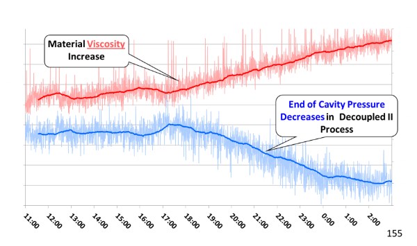
The inverse relationship between viscosity and cavity pressure in a Decoupled II process
Decoupled III: Fills the mold cavity with speed to roughly 85% visually, then packs the cavity with speed to a predetermined cavity pressure before the machine transfers into a fixed holding pressure. Typically, this yields the lowest shrink rate and best consistency over time because of the two stages of speed control and moving the control from the molding machine into the cavity.
Based on part size, tolerance, and material of this application, a Decoupled III is appropriate.
Ball 2: Packing to a cavity pressure increases the stability over time.
Mold Design
So, why is it important to know all of these things before designing the mold? In order to ensure part quality over time, we must select not only the correct type of gates, but also the correct location and quantity of those gates. The mold has to manage the pressure loss through the runner system and the part geometry to ensure the molder can consistently process the material and meet the drawing requirements. Large pressure losses increase the chances of dimensional stability, sinks, and short shots. Typically, a mold designer would look at this part and indicate that a single edge gate on the right side would be more than adequate to fill and pack the mold, as shown here.
Though a single gate would likely do that, we must also consider the tolerances and validation. In order for the mold to be a true success over time, we need to determine the proper number of gates based on comparing the range of shrinkage to the Cpk requirements of 1.33. Based on the previous discussion, the single gate at the end is ineffective, as the expected shrink range is 26 times that of the total tolerance. (See animation above). So, what are our other options?
The first option is to move the gate to the center vs. the end. This will not change the total from end to end, but it will reduce the shrink range from 0.2619 to 0.1309 because the flow length is cut in half. Reducing the pressure loss from the gate to the end of fill promotes better cavity packing and less shrinkage. However, we are still not even close to being in tolerance, let alone capable.
The next option is to put two gates in the part, splitting the overall length into thirds. If this was a cold runner mold, there would be a knit line at the part center, which would a structurally weak point in the part. It would need to be determined whether or not this is acceptable based on product use. By adding two gates, we effectively reduce the flow length to 2.425 in., a quarter of its original length, 9.700 in. This in turn reduces our range of shrinkage to 0.0654 in. Still, this is greater than 6 times the total tolerance range of 0.010 in. and won’t get us where we need to be.
Adding two gates didn’t work, so double it to 4 gates. This would make the flow length 1/5 of the original, so the range is now reduced to 0.0523 in.—still not enough. Plus, there are now more knit lines that will reduce the part strength.
What about five sequential valve gates? This is a more practical response because we need to reduce the flow length of the material to allow for better packing and less shrinkage. The valve gates also help us to remove knit lines if we started filling from the center outward and opening the additional gates after the flow front passes. However, the downside is that with this many valve gates, the structural integrity of the A side is dramatically reduced.

This is where we use flow simulation software like Autodesk Moldflow®, Moldex3D, or Sigmasoft to help us understand the outcomes of our proposed solution.
Foul tip: Still alive but hanging on by a thread.
Conclusion
Making changes after the steel has been cut or—even worse—when the mold is in production can be staggering. Without a scientific approach, it’s highly likely that time-consuming and costly engineering changes will plague the project, pushing it over budget and behind schedule. RJG’s TZERO® Group offers skills, knowledge, experience, and tools to systematically identify problematic areas early on in the project while working within the requirements of the OEM, the mold design, and the equipment at the molder.
Achieving what the part designer wants is not always feasible based on the geometry, tolerance requirements, and material selected. There needs to be a discussion on what is feasible based on physics, product function, and budget. Large automotive parts (like bumpers and door panels) pose a challenge for selecting the correct number of gates based on sheer size. Medical parts with tight tolerances make it challenging due to the tolerances required to produce a mold that can meet ±0.001 in. (or less in some instances). Tighter qualification procedures can make an already frustrating project even more problematic. Semi-crystalline materials like Polypropylene (PP), Polyethylene (PE), and Polyoxymethylene (POM) will only add to this already painstakingly difficult project due to the wide and large range of shrinkage that can be expected.
Knowing the process strategy is critical, as it impacts the shrinkage. It’s not a single variable that causes parts to not meet validation requirements, but rather a stack of items that must be thoroughly evaluated to ensure part quality over the life of the program. The example we have walked through is not a perfect scenario by any stretch of the imagination, but rather a short journey to help you understand what it takes to design and build a mold from the plastic’s point of view.
About the Author

Jeremy Williams
Jeremy Williams has over 18 years of experience in the plastics industry serving the medical, automotive, furniture, and appliance industries. He previously worked as a Principal Engineer, taking projects from design concept to saleable products. Jeremy earned his Master Molder II certification in 2011, became an RJG Certified Trainer in 2012, and started at RJG in 2015. In addition to his extensive manufacturing background, he holds degrees in plastics and business. Currently Jeremy is a Consultant/Trainer with TZERO®.