


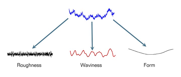
Surface texture is separated into roughness, waviness and form. Photo Credit: Digital Metrology Solutions
Surface roughness is frequently considered a number measured on a gage or the number of a sample on a comparator chart. However, describing surface texture with a number is a lot like describing a concert in terms of decibels: loudness is only part of the story. The Rolling Stones, Tchaikovsky and an angle grinder can all produce 100 decibels, but the whole picture is much more complex and interesting.
More than a number, roughness or more generally “surface texture,” describes the shape of the surface. Texture affects not just the appearance of the molded components but also grip, wear, vibration, noise, sealing, coating adhesion, etc. It also impacts the performance and wear of the tooling itself.


Understanding which aspects of surface texture are essential for a given application is the key to creating durable surfaces that perform well. For example, the finish of a molded gear will have different requirements than that of a sealing surface, knob or sensor component.
Here we’ll look at the nature of surface texture, how it’s measured and analyzed, and what we need to control to improve mold performance, reduce wear and produce high-performing molded components.
It’s critical to understand that changing the roughness may have little or no effect on waviness and vice versa.
Surface Texture Includes Roughness, Waviness and Form
Over the past several decades, measurement equipment and software advances have shaped our understanding of surface texture. Rather than thinking of a surface as having a generalized “roughness,” we now describe surface texture in terms of as various features with varying sizes. The size of those features are described in terms of “wavelength” — ranging from short wavelength roughness to longer wavelength “waviness” and “form error.”
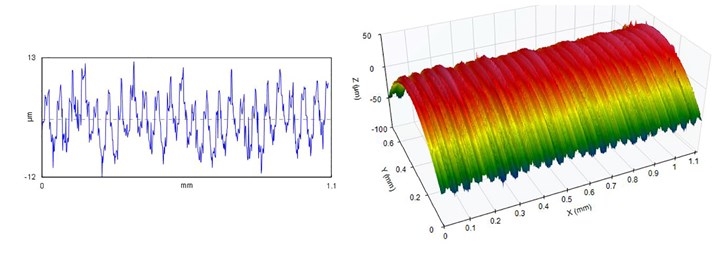
Figure 1. A stylus measurement of surface roughness (left) and a 3D measurement of the surface texture (right). Both measurements show roughness and residual tooling marks that may impact the performance of the molded parts. Photo Credit: Digital Metrology Solutions
Surface texture is measured with a variety of instruments. The most prevalent is the roughness gage, which measures texture by moving a stylus across the surface. The result is a 2D “profile” (Figure 1, left). Noncontact optical techniques are also sometimes used to obtain 3D texture measurements (Figure 1, right). In both measurements in Figure 1, we can see fine roughness peaks but also a larger, periodic shape remaining from a machining operation. Both of these aspects of the texture may affect the final performance of the component, and both may need to be controlled independently.
Very Different Surfaces Could Have the Same Roughness
Comparing a surface to a cosmetic finish card gives a general sense of the texture, though this method is subjective and provides only limited information about the surface. Measuring a surface with a stylus gage or other instrument provides numerical values that can be specified and tracked over time. With modern instruments, the measured surface points can be stored to retain the actual “shape” of the surface for comparison over time.
Surface roughness is often specified using parameters such as average roughness (Ra), which is the average deviation of the surface from the mean height. A “rougher” surface generally has a larger Ra value.
The challenge, however, is that very different surfaces can produce the same Ra value. For example, Figure 2 shows five surfaces with the same Ra but very different characteristics. All of these surfaces might pass a specification for Ra. However, will the component leak or seal? Will it appear matte, dimpled, streaked or smooth?
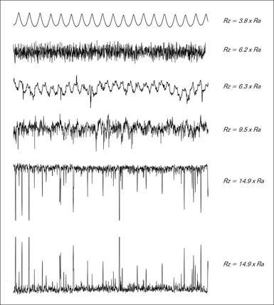
Figure 2. Very different surfaces with the same Ra value. Photo Credit: “The Surface Texture Answer Book”
The average roughness, Ra, may not help us to tell the difference because it does not differentiate peaks from valleys and cannot discriminate narrow spacings from wide spacings between peaks/valleys. If these aspects of the texture affect the component’s function, they need to be controlled using other surface texture parameters.
Waviness May be as Important as Roughness
Another issue is that larger shapes in the texture (waviness) may have as significant an impact on the part’s function as roughness. We can separate surface texture into its component wavelengths through “filtering” to examine its components. A filter attenuates texture above or below a set wavelength. For example, the “roughness cutoff” separates the data into shorter wavelength roughness and longer wavelength waviness (Figure 3).
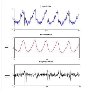
Figure 3. Separating surface texture (top) into longer wavelength waviness (middle) and shorter wavelength roughness (bottom). Both aspects of the texture may be critical to the part’s function. Photo Credit: “The Surface Texture Answer Book”
Filtering allows us to control the texture that matters for the application. For example, Figure 3 shows a milled surface (top). We can clearly see the tooling marks when we filter out the shorter roughness wavelengths. When we remove the wavelengths corresponding to the tooling marks, we can see the finer roughness of the surface.
“Roughness” and “Waviness” are Application-Based
“Roughness” and “waviness” are not fixed ranges of wavelengths. Instead, they will vary based on the application. For example, the lens mold in Figure 4 shows larger structures in the waviness and fine tooling marks in the roughness, both of which will affect the performance of the molded lenses. However, even those larger structures in the waviness would be too small to influence the roughness of a computer mouse shell.
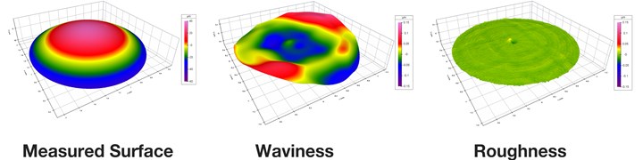
Figure 4. A 3D measurement of the mold for a plastic lens (left), the waviness includes a larger structure that affects lens performance (center) and the roughness includes residual tooling marks (right). Photo Credit: Digital Metrology Solutions
It’s critical to understand that changing the roughness may have little or no effect on waviness and vice versa. For example, polishing a mold surface to a mirror finish may not impact the waviness at all! For optical components, seals and other components, the result of such polishing could be parts that pass roughness inspection but fail in actual performance.
Parameters for Controlling Surface Texture
Early measurement systems only provided a handful of roughness parameters, such as average roughness, RMS roughness, maximum peak-to-valley height and possibly waviness. As measurement technology and processing capability have advanced, it’s become possible to calculate dozens of parameters to look at many additional aspects of the texture, such as spacings between peaks, ratios of peaks versus valleys, etc. (see Figure 5). All of these parameters were developed to track aspects of texture that affect part performance, but could not be discerned by more basic parameters.
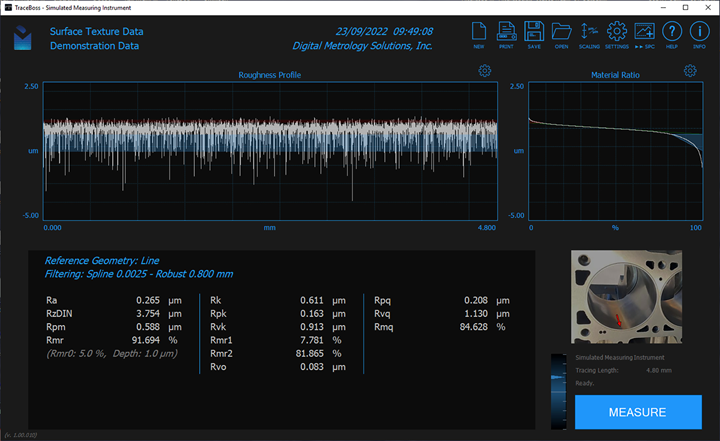
Figure 5. Analysis software includes many parameters to control various aspects of the surface texture. Photo Credit: Digital Metrology
The choice of which parameters to specify and control depends on the application. For example, suppose rough peaks represent a potential issue for feel or sealing, or sufficiently deep valleys are required to retain lubrication. In that case, parameters can be specified to control these aspects of the texture.
The world of surface texture goes far beyond a single number definition. To produce quality surfaces, we need to see and understand what matters about the texture for the application.


Related Content

Mold Maintenance Continues to Matter: Enhanced Training Program in a New Facility
I attended a MoldTrax mold maintenance workshop in 2019 and shared my experiences, and despite changes in ownership, the workshop's remarkable value endures, as discussed in a recent Q&A with the current leadership.
Read More
How to Overcome Complex Mold Texturing Problems
Key benefits when considering laser technology for mold texturing and repair.
Read More
Questions and Considerations Before Sending Your Mold Out for Service
Communication is essential for proper polishing, hot runner manifold cleaning, mold repair, laser engraving and laser welding services.
Read More
Automating Mold Polishing With AI-Powered Robotics
Empowering human workers and harnessing the precision of AI-driven robots may help streamline the polishing process for some molds and tooling.
Read MoreRead Next

Surface Treatments Protect Mold Finishes, Reduce Downtime and Part Failure
Surface treatment vendors are expanding their services to include more treatment options, advanced technologies and convenience.
Read More
How to Use Reverse Engineering to Reduce Mold Tuning Time
Mold builders can reduce the number of iterations required to yield acceptable parts with a new tool, a damaged mold or a copy of an existing tool using modern data collection techniques and advanced surface modeling technologies.
Read More
Examining Mold Surface Quality
High-quality rotary encoders can help improve the quality of milled surfaces.
Read More