
Use Plunging to Increase Metal Removal Rates
Recent cutting tool innovation—as well as new CAM programming techniques—make plunging a more popular approach.


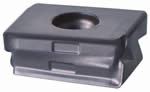
Figure 1: Inserts have four cutting edges and are tangentially clamped on the frontal face of the tool to create a flat surface. This creates a positive rake face for reduced load during machining. Images courtesy of Iscar Metals.
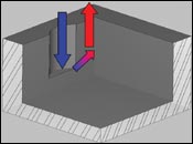
Figure 3: An important programming technique in side plunging is the ability to retract at an angle after the tool has made a cut.
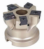
Figure 2: A new side plunger with unique tangentially clamped inserts designed to machine at long overhang and with minimal bending forces.
Plunging—or as it has been recently called in the Midwest, stomping—typically has been an approach saved for long reach roughing applications. When performing roughing applications there are many ways to get the job done—from basic “Z” level roughing using conventional methods (large depth-of-cut, slow feed) to the high speed/feed methods (shallow depth-of-cut, increased feedrates) applied when using modern technologies. For a variety of reasons (programming, power consumption, etc.), plunging is usually turned to only when other methods have proven ineffective/problematic.
Recent cutting tool innovation, as well as new CAM programming techniques, should make plunging a more popular approach, especially on older machine tools that lack the ability to operate at high feedrates.


CAM Programming for Plunging
One of the major roadblocks when attempting to plunge mill is programming.
Toolpath generation for plunging applications can be tedious because most CAM packages have lacked user-friendly options with the ability to adapt to various workpiece geometries (2-D, 3-D, etc.), and plunger styles (side cutting, center cutting, etc.).
An important programming technique for side plunging is the ability to perform some type of angular retract at the bottom of each plunge (see Figure 1). This angular retract becomes necessary when the forces acting on the plunger push it away from the part. What can happen next—without the angular retract—is insert failure due to interference with the workpiece as the tool rapids out of the part.
Cutter Design Improvements: Handling Forces
In side plunging applications, the forces acting on the cutter will cause the cutter to push off/away from the workpiece. How much the cutter deflects is based on a number of factors: tool engagement, feedrate and the rigidity of machine tool to name a few. The geometry of the cutting tool and insert will also greatly affect these forces and this is an area of recent improvement for a new side plunger (see Figure 2).
The ability to press sophisticated carbide inserts has enabled the development of a plunger that cuts using less force and therefore reducing deflection. In most instances, this new technology eliminates the need for the aforementioned 45-degree retract at the bottom of each plunge and programming becomes much easier by allowing the use of the machine tools canned programs for drilling (G81, G85), especially for simple two-workpiece geometry.
Inevitably, some bending forces will result and the insert will engage small amounts of material during retract motions. With this in mind, side relief was added with lead angle, which gives the tool/insert the ability to handle small amounts of material during retract (see Figure 3).
Advantages of Plunging
Machining the workpiece from top to bottom at given intervals (i.e., “Z” level roughing) is the most popular method used for roughing. Recently, machine tools and cutting tools capable of high speed/feed machining have increased the productivity of “Z” level roughing.
This approach can have its limitations when workpiece geometry, machine tool or workholding limits the ability to operate at constant high feedrates (sometimes operating at 200 to 300 inches per minute feedrates). When any of the aforementioned occurs, the advantages of plunging include:
Constant Engagement
When using the Z level machining approach, chip loads (IPT) increase and decrease as variations in radial and axial engagement occur. With plunging, although radial engagement and step-over varies, a constant chip load is maintained.
Optimized Toolpaths
When compared to the Z level approach, plunging is usually a more direct approach requiring less movement (linear inches of machining) to machine a given area. This is especially true when encountering geometries that require multiple XY directional changes (such as a pocket with support pillars).
Optimizing Machine Tool
Plunging removes large amounts of material while moving at relatively low feedrates (more than 50 ipm would be unusual). By implementing plunging, shops with older machine tools can achieve metal removal rates that compare to—and sometimes exceed—newer machine tools running with a high feed approach.
Handling Interrupted Cutting Conditions
In many cases when encountering interrupted cutting conditions, one is forced to reduce the cutting parameters in order to reduce/eliminate the chances of chipping or fracturing inserts. Plunging tends to handle these conditions with more consistent results. This could be attributed to the approach into the material being axial and to the consistent chip load per tooth maintained during plunging.
Dealing with Cutting Forces
The axial forces of plunging typically allow aggressive operating parameters with less concern of moving the workpiece.
Summary
Advanced pressing technologies are leading to the development of cutting tools that reduce cutting forces, are stronger in design and make better use of the carbide raw materials used to make them (i.e., saves money). Plunging will gain in popularity as shops learn they can increase efficiency through greater metal removal rates across a wide variety of applications and materials, as well as increase the capacity of older machine tools.


Related Content

Best Practices for Hitting Critical Numbers: Communication and the Shrinkage Factor
Start with an upfront review, discussion and collaboration with the customer and then consider the shrinkage factor.
Read More
How to Manage Wall Thickness Changes in Your Mold Design
To ensure even filling and cooling, consider wall section transitions, corners and fillets, ribs and bosses, lip and rim designs and CAE flow simulation software.
Read More
Three Good Reasons to Switch from Three- to Five-Axis Machining in Moldmaking
Five-axis machining technology is a great tool in the moldmaker toolbox.
Read More
Mold Design Review: The Complete Checklist
Gerardo (Jerry) Miranda III, former global tooling manager for Oakley sunglasses, reshares his complete mold design checklist, an essential part of the product time and cost-to-market process.
Read MoreRead Next

Plunge Milling Saves Time on Big Mold Cavities
By using a plunge mill, what used to take four hours now takes only 30 minutes—and stretches mold feedstock.
Read More
Overcoming Pain Points in Moldmaking with AI
Shops that embrace AI as a tool, not a threat, can enhance efficiency, preserve expertise, and attract tech-savvy talent.
Read More
How to Use Continuing Education to Remain Competitive in Moldmaking
Continued training helps moldmakers make tooling decisions and properly use the latest cutting tool to efficiently machine high-quality molds.
Read More