


Hot runner temperature control and proper hot runner system management can easily get lost in the day-to-day flurry of tool changes, process setup, equipment issues and myriad other urgent matters. Compounding this challenge is the need to onboard and train new employees on why things are done a certain way and not just how. Here is a guide for training new moldmaking and molding professionals on hot runner temperature control fundamentals.
Getting System Components Production-Ready
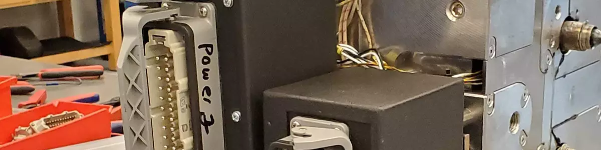
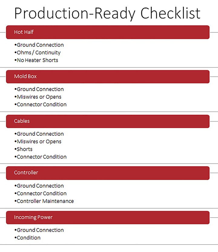
Before turning on a hot runner controller, make sure that what you are about to turn on is production-ready. This preparation will save a lot of time and ensure safe operation.


Five critical areas to consider during this preparation include the (1) condition of hot runner heaters, thermocouples and grounding (ensure there are no direct shorts), (2) mold box connections and grounding, (3) heater and thermocouple cable connections and grounding (ensure there are no direct shorts), (4) hot runner controller connectors, maintenance and grounding and (5) incoming power and grounding. Notice the importance of proper grounding. If any one of these links in the chain is not production-ready, the system will not perform correctly.
To ensure your hot runner system performs correctly, get all of the components production-ready before turning on the hot runner controller. Photo Credit: Fast Heat by Spark Industries.
- Hot Runner Heaters, Thermocouples, Grounding and Direct Shorts
There is no sense in putting a tool into production only to have heater failure, so routinely measure the ohms of each heater within the hot runner system and compare that measurement to its intended rating. You can easily see the resistance rise when you document ohms in a spreadsheet, providing a timeline for proactive heater replacement. Also, an open circuit will be evident when checking ohms if a heater circuit is open or miswired to the wrong hot/return zone in the mold box.
Type J grounded thermocouples (t/c) are the most commonly used. Checking ohms on t/c circuits ensures continuity and consistent readings will identify if there is a reverse. You can determine a shorted t/c by applying heat to the intended t/c location. Ohms should rise. If there is a short (the t/c is closed at a different junction location), you will not see the same reaction.
Grounded thermocouples are susceptible to ground leakage from heaters when there is no effective ground connection between the hot half and the heater connectors. Most modern, integrated controllers have an auto-slave or manual slave option that enables you to run a zone off a comparable zone’s t/c, in the event you lose one. In addition, some mold boxes and controllers provide a thermocouple protection device to address the ground leakage issue.
If a ground wire is securely and cleanly fastened to the hot half and each heater connector in the mold boxes, touch the heater connector legs to the hot half to check for direct shorts. If there is continuity, then a pinched wire or a heater sheath contacting a lead upon heating the system caused a direct short.
Do not plug this tool into a hot runner controller and turn it on. A direct short poses a severe safety hazard and damages thermocouples, connectors, cables and the controller.
- Mold Box Connections and Grounding
The mold box is a transition from the hot half to the heater and thermocouple cables. Based on the wiring diagram, wire each heater and thermocouple to the correct junction in the mold box and then from that junction to the back of the heater or t/c connector point. Some controllers allow reassignment of the thermocouple to a different zone if there is a miswire.
Ensure the heater connectors have a ground wire connected to the mold box and that the mold box is mounted directly to the hot half. The last thing to check is the connector pins and latches. Bent pins and pushed-back inserts are a common issue and a game stopper. Broken or missing latches will cause intermittent connections, leading to intermittent alarms, poor t/c readings and open circuits.
- Heater and Thermocouple Cable Connections and Grounding
Heater and t/c cables have the same potential issues as mold boxes, including miswires, opens, shorts, missing or bad ground, bent pins and pushed-back inserts.
Cables can also have physical wear and tear, especially around the strain areas near the connectors. Ideally, cables should have service tags indicating that they are production-ready.
- Hot Runner Controller Connectors, Maintenance and Grounding
Connectors on the controller have similar issues as connectors on cables. For example, pushed-back inserts, bent or missing pins, broken or bent latches, loose or missing ground wire connections.
The controller will have specific maintenance requirements as well. For example, you must update and clean filters, cooling fans, power module fuses and board components to ensure they function as designed.
- Incoming Power and Grounding
Variable frequency drives (VFDs), servomotors, poor incoming power quality and poor in-plant grounding can negatively impact hot runner temperature control, so make sure that all VFD and servomotors have shielded cables. The hot runner cables should also be shielded and not run parallel to high-voltage lines. If the facility’s earth ground is inadequate, you may have to drill a hole in the floor and drive a copper grounding spike at the machine.
Proper Hot Runner Bake-Out and Sequential Heating
The heaters within a hot runner system are hygroscopic, meaning that the moisture absorbed during mold storage can create a short. Therefore, most controllers will have a bake-out function that uses a small percentage of power that slowly increases to bake out this moisture.
Depending on hot runner controller features, you may be able to automatically heat the hot runner system by assigning groups (manifold primary, manifold secondary, sprue, cavity and so on). For example, bringing the largest masses up to temperature first. Then, the next group is second, third and so on until the final group reaches the setpoint (see diagram).
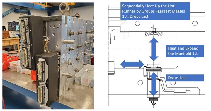
Some hot runner controller features can automatically heat the hot runner system by assigning groups.
If you’re using a less advanced controller, you may need to turn on one group at a time manually. Unfortunately, simultaneously turning on all of the groups can damage the hot half at the mating surfaces. This may also cause wear around the gates, degrade material in the drops or even “spit out” hot plastic from the nozzles.
Reading Temperature
A grounded type J t/c has an iron (+ white) lead welded to a constantan (- red) lead with the outer sheath at the tip of the thermocouple, creating a single junction point. When this junction point is heated, it creates a voltage. This millivolt reading is correlated to a temperature and then displayed. Therefore, the read frequency and display updates of controllers will vary.
The t/c location will have a significant impact on process control. Your hot runner supplier and mold builder can provide advice on how to best manage a particular mold. For example, it may be best for thin-wall fast cycle applications to put the zones into manual percent power rather than track the melt flow’s ups and downs. A manual mode is also a good option for shorter sprue bushings.
PID Control and Power Output
The PID (proportional, integral, derivative) is a vital element of a hot runner controller. Every controller will have a unique way of comparing the temperature reading with the desired setpoint and then applying the right amount of power to close the gap without significantly over or undershooting. The term “fuzzy logic” is often used to explain how a controller attempts to tighten this up.
The two main approaches to applying power are zero-cross over and phase angle. These power outputs assign a percentage of power. A day-to-day operator of a hot runner controller will likely not notice the difference, but controller engineers strategically leverage these approaches to achieve the desired controller performance. Ultimately, the “proof is in the pudding,” so trials are essential for demonstrating the effectiveness of one controller versus another.
Most advanced controllers have an alarm band for percent power, which helps detect a leak within the hot runner system. For example, when a nozzle begins to leak, the percent power required to maintain set point will spike. Using this alarm to stop production will prevent flooding a mold.
Auxiliary I/O Options
Some controllers have three I/O connection options: contact relays, five-volt or 24-volt inputs and outputs. These are simple to set up and use to tie the hot runner controller into the injection molding cell.
Here are some examples of how to use I/O connections:
- Percentage power alarms turn off zones and the controller and serve as an output to stop the molding machine.
- Temperature alarms change conveyer direction, so parts drop in an inspection bin.
- Increased injection pressures send a signal to the controller to boost the tip temperatures.
- A signal from the molding machine automatically idles zone temperatures (for example, if production stops, temperatures are automatically boosted to restart production).
- A soak timer from the controller to the molding machine provides the all-clear to inject.
- Preheat stations automatically boost zone temperatures before shuttling into the molding machine.
Trends in Industry 4.0 are taking molding cell integration even further with remote monitoring, control and data streaming.


Related Content

Hot Runner Systems, Controllers, Auxiliary Injection Unit Exhibitions
Mold-Masters exhibits a wide variety of new and enhanced systems and technologies at K Show like the TempMaster manifold plastic leak detection, the PET-Series two-stage hot runner system and Fusion Series G3.
Read More
Standard Hot Runner Cable Range Extension
Hasco is now offering its H12251 cable in two different lengths and four different wiring standards.
Read MoreRead Next

Getting Hot and Heavy during a Little Hot Runner Training
If a mold is the heart of a molding system, then the hot runner system is the heart of a hot runner mold, and I recently learned that there is a lot to know when it comes to designing and maintaining these systems to ensure optimal mold and part quality and performance.
Read More
Maintaining a Strong Relationship with Your Hot Runner Supplier
Once your hot runner supplier is chosen, you need to take the proper steps to maintain a mutually beneficial, long-term relationship.
Read More
Are You a Moldmaker Considering 3D Printing? Consider the 3D Printing Workshop at NPE2024
Presentations will cover 3D printing for mold tooling, material innovation, product development, bridge production and full-scale, high-volume additive manufacturing.
Read More