
What’s All the Chatter about Aluminum?
Special cutter geometries can virtually eliminate vibration in machining of aluminum molds.
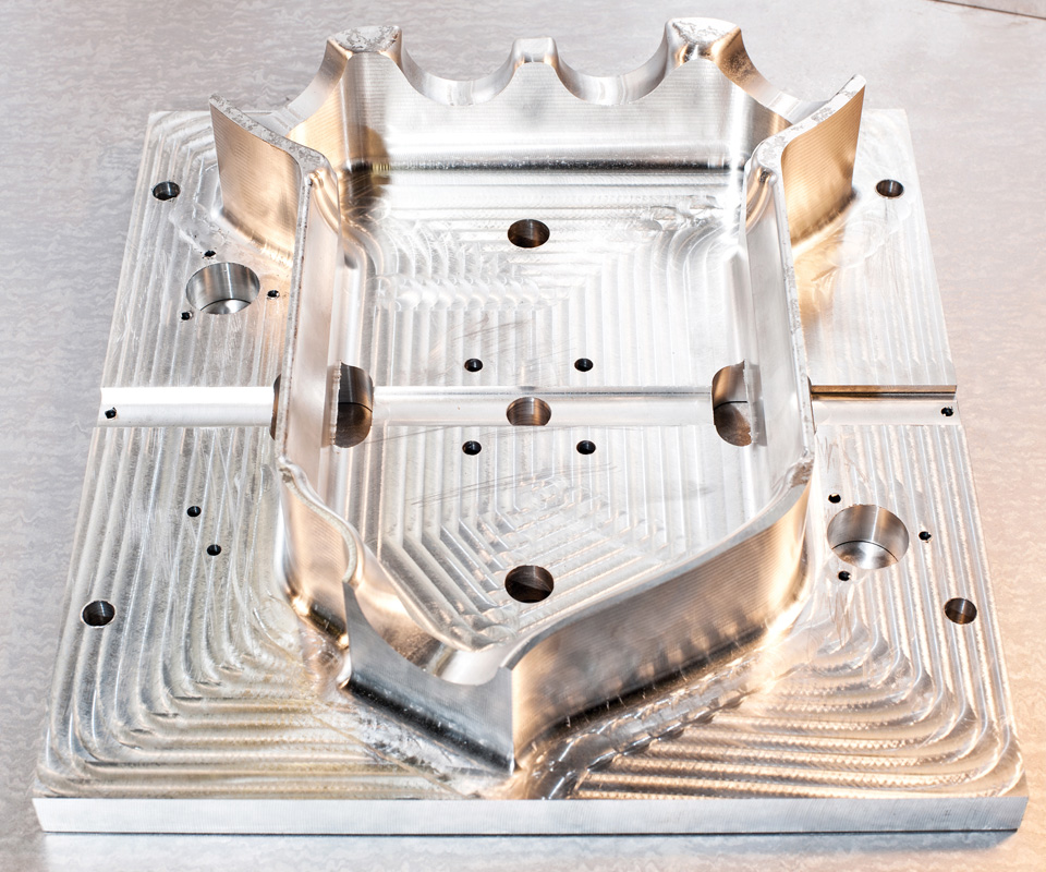
One of the challenges that moldmakers face in looking to improve cutting tool performance in machining of aluminum molds is chatter, or vibration. Images courtesy of RobbJack Corp.
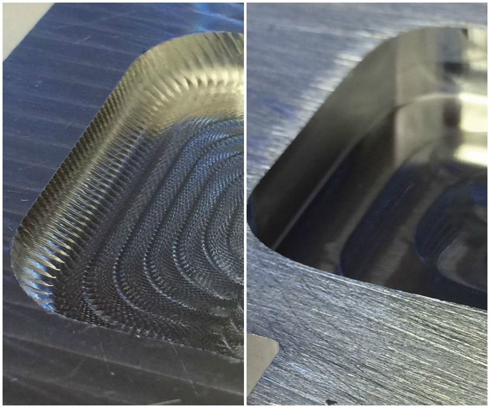
The poor finish on the aluminum part on the left was caused by chatter and vibration. A mirror-edge geometry cutter designed to make the tooth-passing frequency match the part frequency at any speed eliminated all vibration, giving the aluminum part on the right a fine finish.
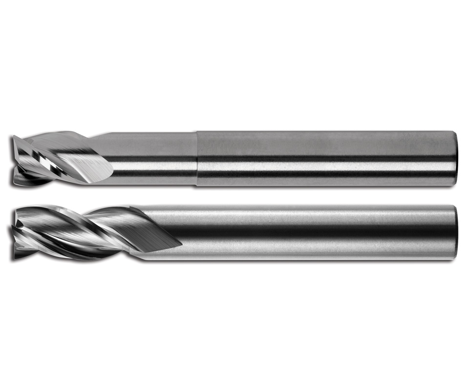
On cutters with vibration-cancelling geometries, tooth-passing frequencies always match the part frequency, allowing mold builders to consistently run the maximum spindle speed available on the machine without producing chatter or vibration.


As demand for faster turnaround has grown, product lifecycles have shrunk and pressure for reduced cycle time has increased, the use of aluminum molds has expanded, thanks to the material’s many inherent beneficial characteristics. These include its light weight, ease of machining, thermal conductivity and polishing suitability, to name a few. Despite these benefits, however, moldmakers do face challenges when looking to improve cutting tool performance in machining of aluminum molds.
Chatter, or vibration, is the most frequent difficulty that arises in cutting of aluminum. The reason chatter is more prevalent in aluminum versus other materials is the increased cutting frequencies within common aluminum machining parameters. For example, parameters for spindle speed (in rpm), engagement angles and metal-removal rates are much more aggressive in machining aluminum. Plus, its lighter, less dense structure enhances vibration rather than dampen it the way harder, denser materials do.


Defining and Calculating Chatter
Chatter is “self-excited” vibration caused when a cutter’s tooth-passing frequency interacts with the natural frequencies of the spindle and the part. As the vibration increases, the noise it produces gets louder, part surface finish becomes poor, machine accuracy decreases and tapers begin to rust (fret corrosion or fretting). Twenty minutes of very bad chatter cutting has been known to make a brand-new spindle taper look like it has been rusting in a junkyard for 30 years. Chatter is not only uncomfortable to listen to, but reduces cutter and machine tool life. Eliminating vibration can help avoid all of this.
A combination of complex formulas, hardware and software can be used to solve chatter problems, but this requires a lot of time and investment. Typically, it involves mathematically calculating the correct cutter speed to make the tooth-passing frequency match the natural frequency of the part. The end result is a very specific setting to be used for each machine, tool “stick-out” (the distance from the tip of the tool to where the tool shank enters the toolholder) and application.
Say, for example, a ½-inch end mill sticking out 2.5 inches on machine “A” requires a speed of 21,454 rpm to eliminate chatter. If the tool sticks out 0.050 inch more, however, a speed of 18,765 rpm might be necessary to eliminate the chatter. To add even more complexity to this scenario, a shop could have five machines that are of the identical brand and model, yet the required speed could be different for each machine. For the mold builder, this approach to solving the chatter problem is not very practical. There are too many variables, and the molds being machined change often, so it is difficult to apply this method to every job and part that must be cut.
Another approach to reducing chatter is decreasing cutter speed. However, this will negatively affect metal-removal rates and cycle times. In extreme applications, the cutter speed might have to be reduced to 2,000 rpm to eliminate chatter, and then the time it takes to machine the mold can increase by 10 times or more.
Parts with longer length-to-diameter ratios (L:D) are more susceptible to chatter, because the cutter’s stiffness is reduced when the tool has to stick out farther from the toolholder. Because extreme L:D ratios are common in molds, most mold builders battle chatter problems. Some will use a series of cutters of different lengths to reach deep into a part. For example, in order to get a ½-inch cutter to reach 3 inches into a part, a mold builder may first use a cutter with 1.5-inch stick-out to remove as much material as possible at what is considered a good removal rate, then move on to a cutter with 2.5-inch reach to remove as much additional material as possible at more conservative speeds and feeds, “babying” the cutter to keep it stable. Finally, he might come in with the 1/2-inch cutter and machine the 3-inch total depth at a painfully slow feed rate with very light cuts.
There are a couple problems with this technique, however. First, it takes three separate cutting tools to machine the mold, increasing tool costs. However, the real pain is felt with the finish of the part. Because each cutter used has a different stiffness, the surface finish each produces varies. For a mold on which surface finish is paramount, this causes headaches and requires very time-consuming blending and/or finishing operations. Programming also becomes complicated with this multi-step process. If the moldmaker uses a long-reach tool from the beginning that allows the machine to move as fast as it is capable without producing chatter, a lot of time is saved and headaches are avoided.
Tool Geometry Can Beat Chatter
Special cutter geometries exist today that are specifically designed to eliminate chatter, regardless of the application. Their tooth-passing frequencies will always match the part frequency, whether the spindle is spinning at 40,000 rpm or 2,000 rpm. This allows the mold builder to consistently run the maximum spindle speed available on the machine without producing chatter or vibration. This, in turn, means he can cut material faster without producing poor surface finish, and it increases cutter and spindle life.
This vibration-cancelling geometry at the end mill’s extreme cutting edge causes the vibration of the part and the vibration of the end mill to match frequencies. Things are still vibrating, but they are vibrating in unison, so the part and the cutting edge are at the same place in space as the flute cuts the material. Each flute cuts the exact amount of material that it is programmed to remove. When chatter is present, each tooth is making erratic cuts in the material, causing the chip load to be extremely heavy on one flute and preventing the following flute from contacting the part. This erratic engagement of the cutter perpetuates the problem and causes the self-excited chatter.
For parts with longer length-to-diameter ratios, vibration-cancelling geometry permits the use of a long tool, but without the typical problems. For example, it yields consistent surface finish throughout the part, no resultant mismatched areas where the cutter deflected differently and no surface-finish changes from tool to tool. Some shops cutting aluminum in extreme L:D ratios have even reported a cycle-time reduction of more than 1,000 percent, and they were able to reduce the number of cutting tools from five of different lengths to one, simplifying and maintaining consistent surface finish.
Tool paths are also key to reducing chatter and mismatched finishes. Instead of zig-zag tool paths that create a pendulum effect with the cutter, climb-cutting the part is recommended. This can be achieved by constant Z-level cutting or trochoidal-type cuts. Pressures and deflection remain the same if a cutter does not move from a climb to a conventional cut. This is where climb-cutting tool paths can really help. Modern CAD/CAM systems can control the amount of cutter engagement with the material and keep the surface contact constant throughout the cut, simplifying programming.
In a nutshell, vibration-cancelling cutter geometries can improve aluminum mold machining by eliminating chatter, increasing cutter stick-out, and removing the need to use multiple tools or to slow spindle speeds. Add to that newer tool paths that keep the cutter constantly engaged in the cut in a climb-mill direction, and mold builders can also improve aluminum mold finishes.


Related Content

How to Overcome Cutting Tool Vibration
Advanced indexable milling cutting tool design provides secure, predictable machining, increased metal removal rates, reduced cycle times and fast changeovers.
Read More
Precision Meets Innovation at IMTS 2024
After attending IMTS, it's clear that the integration of advanced technologies is ready to enhance precision, efficiency and automation in mold manufacturing processes. It’s a massive event, so here’s a glimpse of what the MMT team experienced firsthand.
Read More
Ten Things You Need to Know about Circle Segment Milling
Considerations for evaluating if circle segment end mills or conical barrel cutters are right for your mold machining applications.
Read More
Why Mold Builders Should Consider Barrel Cutters and Lens Tools If They Haven’t Before
Reduce machining cycle times and improve surface finishes of cavity and core work with barrel cutters and lens tools.
Read MoreRead Next

Your Guide to Smarter, Faster Mold Design
Dive into expert-curated content delivering proven solutions for mold optimization, manufacturability and precision performance.
Read More
How to Use Continuing Education to Remain Competitive in Moldmaking
Continued training helps moldmakers make tooling decisions and properly use the latest cutting tool to efficiently machine high-quality molds.
Read More
Overcoming Pain Points in Moldmaking with AI
Shops that embrace AI as a tool, not a threat, can enhance efficiency, preserve expertise, and attract tech-savvy talent.
Read More