
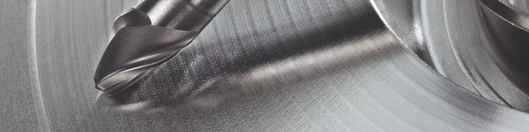


A taper form circle segment end mill cut this mold — a modified part of a core for an aluminum die-cast die for an automotive gearbox. Photo Credit: OPEN MIND Technologies and EMUGE-FRANKEN
You may have heard about circle segment end mills, but do you know if these cutting tools are right for your mold machining applications? The advantages of these cutters can include increased tool life, superb finishes and significantly reduced cycle times as they use a cutting edge with large-profile radii, which leads to a much wider stepover when cutting.
Here are 10 questions to ask that will help you start your evaluation:


1. Do I need to use a particular CAM software?
CAM software must support circle segment milling. When circle segment end mills made their debut approximately five years ago, there were initially just two CAM software packages that could support the tools correctly and efficiently. That number has grown. Today, several CAM packages support the entire line of circle segment end mills. Contact your CAM provider or support technician to ensure they can support circle segment milling and guide your team through the steps to implement the tool successfully.
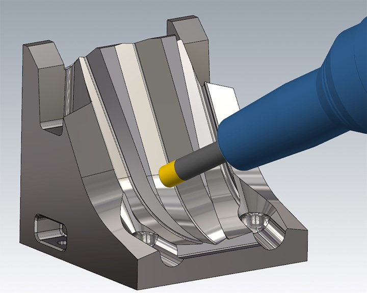
For example, some surfaces could be machined using tangent plane machining in a large fascia mold. Since these pockets are quite deep, the most significant benefit is achieved in areas that cannot easily be machined by side milling with an end mill. Traditionally, they would have to be machined using a ball nose end mill with a tight stepover. The larger the ball end mill, the greater the amount of material that will need to be removed in the corners. Circle segment end mills can easily access these vertical corners and the floors of deeper pockets.
The appropriate CAM software enables circle segment cutting tools to access the vertical and steep areas with tangent plane machining and any flat or shallow areas. In this specific example, it is essential to note that the ball nose end mill took approximately nine hours and 36 minutes to complete. In contrast, the circle segment end mills took an estimated machining time of only one hour and 10 minutes. This accounted for an 88% reduction in machining cycle time.
2. Is a five-axis machine required?
A five-axis machine is preferred for circle segment milling. To maximize the workpiece, you must index the circle segment cutting tools at angles to access corners and intersections of floors and walls. A multiaxis machine enables this versus a conventional three-axis machine fixed only at 90º and cannot rotate to any angle.
However, sometimes three- and four-axis can also work when part features and the right cutting tool work well together. For example, using an oval form circle segment cutting tool on a three-axis machine can enable the ideal surface contact of a steep wall pocket. The only way to know if it is possible is to test the cutting tool in your CAM system and view the simulation back plot. Having the right CAM in place will ultimately significantly impact researching the possibilities of implementing circle segment milling.
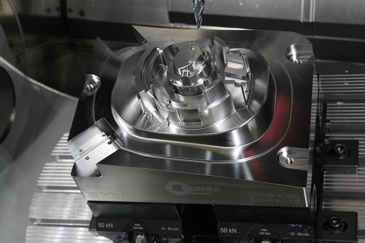
A 10-millimeter-diameter lens form circle segment end mill in position. The tool-cutting radius callout is 20 millimeters, representing the diameter of a 40-millimeter-diameter ball. Photo Credit: Mastercam and EMUGE-FRANKEN USA
3. Are circle segment end mills adaptable to different materials?
Circle segment end mills are highly versatile and can be used in virtually all materials. Referring to material specs showing SFM and chip load will help you choose the right cutting tool. For example, when machining aluminum, use a three-flute taper form instead of a six-flute version. In softer materials, operators tend to get more aggressive with depth-of-cuts. A three-flute taper form enables chip evacuation and a six-flute taper form is better suited for mold steels up to 60 Rc. It is also advised to follow climb-cutting directions for optimal results in surface quality.
4. How does part geometry factor in?
A mold core or cavity with steep planar walls or gradually curved wall features in parts — such as a plastic cutlery storage tray that fits in a kitchen drawer — will adapt to a nice flowing circle segment toolpath. On the other hand, a mold core or cavity of a spoon or fork is an example of non-desirable part geometry.
The intricate surface details of the curve of a spoon or the prong of a fork are best machined with a traditional ball mill. However, this application would be a square peg in a round hole scenario for circle segment milling because there is not enough surface area to fit the cutting tool.
For high-production mold and die shops that manufacture high volumes of the same mold type, it is a good idea to review potential cost reductions in machining cycles when using circle segment milling.
5. Is surface area (large or small) a consideration?
Whether large or small, always evaluate the surface area when considering the use of circle segment end mills. For example, perhaps a section of the part would benefit from implementing circle segment milling.
For high-production mold and die shops that manufacture high volumes of the same mold type, it is a good idea to review potential cost reductions in machining cycles when using circle segment milling. But, again, the advantages will become clear once you understand how the tool is used and how to engage the part.
6. What cycle time reductions can I anticipate?
When using circle segment end mills instead of a ball mill for surfacing, you could experience between 70-95% cycle time reductions with an improvement in surface finish quality. The part geometry is vital for cycle time reduction opportunities.
7. How do I determine which circle segment cutting tool style to use?
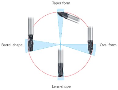
Circle segment end mills are offered in four geometries: barrel-shape, oval, taper and lens-shape. Oval and taper form mills are ideal for curved shapes such as blades or straight-walled pockets, freely engaging more of the cutting edge. Barrel design mills provide highly effective flank milling to the sides of spiral grooves and similar applications, while lens-shape mills excel in narrow channels or in lands on molds. Each type is available in various diameters and lengths depending on the type of application.
Here are two reasons to start with the taper form as the initial tool when reviewing an application:
- It has the longest reach capabilities with a stub flute length-of-cut with a 1,500-millimeter profile radius. The large defined radius allows for a larger axial depth-of-cut (DOC).
- It has an identified required angle tilt of 20º, providing more holder clearance. If 20º of clearance is not enough, review the taper form with the 200-millimeter profile radius with a tip angle of 42.5º.
8. How do I determine the proper speeds and feeds?
Circle segment tools have materials listed with the appropriate cutting data to handle the application successfully. Recommended feeds and speeds will produce optimal results, but it is also important to understand that part setups, machine capabilities and toolholding are not always optimal. Therefore, there is a good chance that speeds and feeds can be increased once these variables are optimized.
9. Are circle segment end mills primarily used for finishing?
Circle segment end mills are considered finishing tools. Still, taking multiple steps to get to the final size is possible, provided that you do not exceed the recommended radial depth-of-cut.
10. What role does the end mill manufacturer have?
Knowing that you do not have to go it alone is essential. You should partner with a cutting tool manufacturer well versed in circle segment technology and circle segment end mill designs. Also, since specialized programming is sometimes required for circle segment milling, choose a cutting tool manufacturer who works closely with today’s leading CNC software companies for programming assistance and process recommendations (e.g., simple programming suggestions, actual program codes and optimized tooling recommendations).
It is also helpful to receive detailed reports with programming instructions, and where applicable, actual sample test cuts with video documentation. Finally, working with a cutting tool manufacturer that offers to run test cuts on actual parts or sample materials in their five-axis machining centers is invaluable. As a result, you do not have to tie up your production, saving you time and costs.
Circle Segment Milling Defined
A superb surface finish quality is achieved by mapping only a part of the circle (a circle segment) on the end mill. This end mill design also features unique forms with large-profile radii in the cutting area of the end mills, enabling large stepovers that cut wider swaths of material and fewer tool passes while maximizing tool life, efficiency and minimizing cusps.
The large stepover produces higher cutting forces than standard ball nose cutters due to the large radii on both the face and radial cutting edges. To produce radii this large with a traditional ball nose end mill, the ball nose cutting tool would need to be up to 3,000 millimeters in diameter or even larger.
By combining advanced cutting-edge geometries with expansive radius profiles, circle segment end mills mimic large-diameter cutter profiles with standard tooling sizes. For example, a 16-millimeter-diameter end mill can have a 500-millimeter radius profile, significantly increasing the stepover width of the end mill and reducing milling cycle time by up to 90%.


Related Content

3D Printing Enables Better Coolant Delivery in Milling Operations
Just like 3D printing enabled conformal cooling channels in molds, additive manufacturing is now being used to optimize coolant delivery in cutting tools.
Read More
MoldMaking Technology's Most-Viewed Content 2022: Products
MMT shares the five top-viewed technologies, equipment and services of 2022 in each Engineer, Build, Maintain and Manage tenet based on Google Analytics.
Read More
6 Ways to Optimize High-Feed Milling
High-feed milling can significantly outweigh potential reliability challenges. Consider these six strategies in order to make high-feed milling successful for your business.
Read More
Modular Tooling Systems Enable Versatility in Hole-Drilling Operations
The versatility of replaceable cutting edges offers users the ability to adapt to varied operations.
Read MoreRead Next

Barrel Cutters Going Mainstream?
This CAM developer is gearing up to release a new toolpath strategy for new standard-issue, circle-segment cutting tools that promise big gains in tool life, surface finish and cycle time.
Read More
Cutter Considerations for Hybrid Additive Manufacturing
Four tips for applying the right cutting tools in hybrid additive manufacturing.
Read More
How a Small Programming Change Cuts Cycle Time in Half
Overriding the CAM system when milling a series of lifter pockets helps to improve metal removal rate and increase feed rates.
Read More