
Unconventional Strategies for Roughing
Arc of contact and average chip thickness are essential for optimizing rough-machining operations.
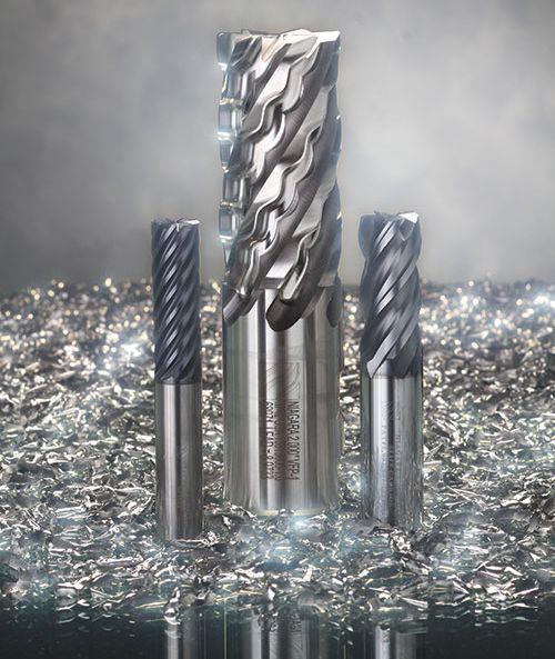
An option for rough machining, these solid carbide multi-flute end mills offer unequal flute spacing, smooth cutting performance, improved workpiece surface finish and increased feed rates. Images courtesy of Seco Tools.
This solid carbide high-feed end mill was designed to maximize productivity in hardened steels and superalloys. Its optimized substrate, geometry and coating are designed to improve performance and process reliability.


Multi-Flute and High Feed
In todays’ competitive manufacturing environment, shop managers are constantly looking for process improvements that will help them reduce costs and save time. More and more shops are turning to advanced machining strategies to reduce machining cycles, especially during roughing stages. Unconventional strategies like high-feed milling, trochoidal milling and dynamic milling have grown in popularity as manufacturers strive to reduce the costs associated with the often-expensive process of preparing individual parts for final machining.
These CAM-based rough-machining strategies are centered on a cutting tool’s arc of contact and average chip load. By manipulating the tool’s arc of contact through its CAM-generated tool path, shops can boost roughing speeds, effectively control process temperature and apply higher feeds per tooth. Additionally, many shops have found that they can also increase depths of cut to significantly shorten overall machining cycle times—all without placing any additional strain on machine tool spindles.


The Arc of Contact Principle
Arc of contact is an independent variable that influences thermal load on the cutting tool, and it is the key to most optimized roughing operations. The maximum arc of contact on any tool is 180 degrees, or its diameter. Consider a slotting operation or a stepover value of 100 percent. At a full arc of contact, the radial cutting depth or cutting width (ae) is the same as the cutter diameter (Dc).
By manipulating the arc of contact, a shop can reduce the amount of heat generated during roughing operations. As the radial depth of cut is decreased, so is the cutter’s arc of contact. Less contact results in less friction and therefore less heat between the tool’s cutting edges and the workpiece it is machining. The tool’s cutting edges have more time to cool from the time they exit the cut, revolve and re-enter the cut. The resulting lower machining temperatures then allow for increased cutting speeds and shorter cycle times.
Average Chip Thickness and Physical Load
Chip thickness constantly changes during cutting, but a cutting tool’s average chip thickness (hm) is based on the physical load and is maintained through a combination of adjustments to feed per tooth and the arc of contact. A full 180-degree arc of contact will generate the thickest chips at the center of the cutter’s width, so a smaller arc of contact (less than 90 degrees) will reduce the chip thickness, allowing for increased feed per tooth (fz) as compensation.
Cutter Designs
Some cutting tools are designed to cut specific materials, while some also offer geometries for advanced machining methods. In advanced CAM-based rough-machining strategies, certain changes to tool design can address chip control as well as necessary flute and length requirements.
When a steady arc of contact is maintained, these tools can experience consistent and evenly distributed wear along their flutes and offer more predictable tool life. However, long cutters produce equally long chips that can be difficult to evacuate from cutting zones and the machine tool.
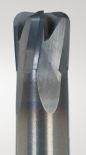
To create chips that are smaller and more manageable, some cutter designs include chip splitters, which are tiny grooves on the tool’s cutting edges and reliefs. Such chip splitters are spaced apart at a distance equal to one time the cutter diameter. So a cutter that is 40 mm long and 10 mm in diameter will produce chips no longer than 10 mm that are quickly evacuated from the cut zone and will not jam machine tool chip conveyors.
With a small arc of contact, the more flutes a cutter has, the faster it can feed and the higher the productivity. Feed speed is equal to the number of cutter flutes multiplied by the feed per tooth multiplied by the spindle speed. While roughing cutters typically have a maximum of four flutes, current research is exploring the potential of five-fluted cutters for increasing productivity.
Complex Shapes and Materials
In straight-line machining paths (side milling), the arc of contact remains unchanged once it is set. However, with a more complex part shape, for example one that includes inside and outside radii, the set arc of contact can be inconsistent. When the cutter finishes a straight cut and engages an inside radius/corner, its arc of contact increases and the cutting parameters no longer coincide with the set arc of contact. If tool paths fail to adjust for these situations, chatter, vibration and cutter breakage can occur.
Today’s CAM packages offer toolpath strategies specifically for inside/outside radii shapes in which changing arcs of contact occur along conventional tool paths. These software packages automatically apply different feeds to control the arc of contact and keep chip loads consistent. To maintain the arc of contact, the software employs trochoidal machining and peel-milling techniques when entering a radius. Next to the chosen tool paths, it can significantly reduce “L” movement to further reduce cycle times.
Picture the tool traversing in a straight line and then changing direction with a 90-degree turn. Regardless of the precision, accuracy and speed of the machine, cutting will decelerate and accelerate during the direction change. This constant acceleration/deceleration can have a significant effect on overall tool life and eventually on machining costs.
Using an optimized roughing tool path and maintaining consistent arc of contact, the cutter’s radius can match that of the inside radius being cut without risk of cutter overload, grabbing or overcutting. This capability allows more stock to be removed in the roughing pass, reducing the amount of stock that must be cut in the finish pass. This translates to faster machining cycle times.
Optimized roughing strategies also apply to specific workpiece materials. Recent testing with steel, stainless steel, cast iron, titanium, aluminum and steels as hard as 48 HRc has established optimized speed and feed data for specific arcs of contact. This testing has determined that a radial depth of cut to diameter ratio of 10 percent should first be applied (5 percent for tough-to-machine materials such as titanium and super alloys). Larger radial depths of cut can be applied, but then cutting speed and feed per tooth must be reduced.
On machines that are unable to handle heavy roughing cuts, the arc of contact can simply be reduced and a trochoidal machining path can be used. This reduces cutting forces and lessens the need for high machine power, yet it still generates high productivity by applying large depths of cut.
When roughing strategies are applied to difficult-to-cut materials such as stainless steel and titanium, coolant should be applied to the complete length of the cutter (top, middle and end). Compressed air at maximum pressure should be used to blow chips away during cutting of steel and cast iron.
One shop that rough-machined a motorcycle component mold reduced its machining cycle time from 900 minutes to 400 minutes by using optimized roughing and tool paths. To accomplish this, the shop used an indexable high-feed cutter for the first and second roughing operation, and then switched to a modified 25-mm-diameter cutter for the first and kept the high feed on the second one.
Summary
Arc of contact and average chip thickness are essential for optimizing rough-machining operations. Using CAM software specifically for toolpath optimization and dynamic milling enables shops to manipulate and control a cutting tool’s arc of contact and maintain consistent loads. This allows for effective control of process temperature, the application of higher cutting speeds and feeds per tooth, and increased depths of cut to significantly shorten overall part machining cycle times.
However, optimized roughing requires the right CAM for external programming. While most cutting tool suppliers offer products designed to cut specific materials, few develop tool geometries for the particular advanced machining cycles and tool paths required. With the right cutter and dynamic cycles, shops can increase metal removal rates by as much as 500 percent compared to traditional machining methods.


Related Content

Ten Things You Need to Know about Circle Segment Milling
Considerations for evaluating if circle segment end mills or conical barrel cutters are right for your mold machining applications.
Read More
Modular Tooling Systems Enable Versatility in Hole-Drilling Operations
The versatility of replaceable cutting edges offers users the ability to adapt to varied operations.
Read More
How to Optimize Mold Finishing
Circle segment technology requires fewer tool paths, improving surface quality and increasing cutting tool life.
Read More
End Mills, Drills, Inserts and More for Mold Building Needs
This list of cutting tool-related products that MMT editors have recently published provide readers a good look at what is being offered in the industry for their everyday operations.
Read MoreRead Next

Supercharging Rough Machining Performance with Advanced Tooling
What is amazing is that the shop is confident it could run the Seco cutter at 500 ipm if the machine was capable. It is this reason that Build-A-Mold is in the process of acquiring newer, faster equipment.
Read More
Your Guide to Smarter, Faster Mold Design
Dive into expert-curated content delivering proven solutions for mold optimization, manufacturability and precision performance.
Read More
How to Use Strategic Planning Tools, Data to Manage the Human Side of Business
Q&A with Marion Wells, MMT EAB member and founder of Human Asset Management.
Read More