
Tooling Up for Mold Machining
Consider machine tool capability, intended milling techniques, programming, workholding and toolholding during your cutting tool selection process.
In high-feed milling, machine stop and start scenarios in the toolpath should be avoided because any amount of machine hesitation when changing directions generates heat that transfers to the cutting tool.
During high-feed operations, cutters should be run at full diameter engagement and no less than half their insert width, which is possible because high-feed cutters effectively direct cutting forces at the machine spindle in the axial direction to create balance.

The three most common insert failure modes of high-feed milling are flank wear, thermal cracking and chipping.


As milling techniques and tooling technology continue to advance, more mold manufacturers are taking advantage of the developments for optimizing machining operations, reducing cycle times and producing far superior mold surface finishes. However, factors such as machine tool capability, intended milling techniques, programming, workholding and toolholding are a necessary part of the equation during cutting tool selection. Equally critical is the ability to analyze worn cutting inserts in an effort to maximize tool life and predict tool usage in mold machining applications.
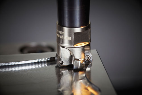
Today’s fast and powerful machine tools with increased programming capabilities are essential when it comes to taking full advantage of the latest cutting tools and incorporating highly effective milling techniques. High-feed milling and high-speed milling are two popular milling techniques that require certain types of cutters for operational success.
Milling Techniques
High-speed (or dynamic) milling techniques are becoming increasingly popular. They are also particularly effective when using solid carbide cutting tools. This milling method is an optimized roughing approach that combines large cutting depths with relatively small radial engagements when cutting steel. This technique is also effective when machining materials 60 Rc and harder.


For high-feed milling, large indexable insert cutters designed for that purpose are recommended to remove the majority of material. Essentially, the process starts with relatively large indexable insert cutters for roughing, and works down to smaller-diameter indexable ball nose cutters and solid carbide cutters as the mold approaches near net shape.
Appropriate cutter diameters are determined based on mold features—such as corner radii. High-feed indexable insert cutter diameters are usually 0.625” and larger. If smaller cutters are needed, solid carbide end mills should be used.
Inserts for high-feed indexable cutters can vary depending on workpiece material, but most applications will dictate a PVD-coated or CBN-coated insert. As for insert geometry, Trigon-style inserts provide the lowest possible lead angle over round or square inserts. Low lead angles produce a much thinner chip, which in turn requires higher feedrates to maintain proper chip thickness for the insert geometry. The lower lead angle also directs the cutting forces in the axial direction, pushing up into the spindle, which is more stable and easier on the machine. Higher lead angles create thicker chips requiring less adjustment in feedrate. They also produce more radial force, causing vibration and stress on the spindle bearings.
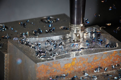
Solid-carbide cutters used for high-speed milling are typically four-flute shoulder end mills with long cutting edges and built-in chip splitters. The chip splitters break up chips into small, manageable sizes—resulting in improved evacuation from the cutting zone, as well as from the machine. Additionally, full cutting lengths and chip splitters—when combined with high-speed milling— generate increased levels of productivity and significantly higher tool life due to consistent loads.
During high-feed operations, cutters should be run at full diameter engagement, but no less than half their insert width. Full diameter engagement is possible because high-feed cutters effectively direct cutting forces at the machine spindle in the axial direction to create balance. Cutters engaged at less than half their insert width will experience push and increased vibrations because the cut is unbalanced.
For high-speed milling, the same types of tools (indexable insert cutters and solid-carbide end mills) used for high-feed milling apply. However, this tooling must incorporate geometries that are conducive to high rpms and high feedrates, but moderate chip loads as opposed to heavy ones.
While high-feed mills with long overhangs are effective, used in high-speed operations they cannot be run as fast as tools with shorter overhangs—unless specialized vibration dampening toolholders are used or cutting speeds are reduced significantly. When a tool with long overhang operates faster than recommended, vibration increases causing insert chipping and premature insert failure.
Insert-Wear Analysis
Maximum tool life and predictable tool usage to maintain part accuracies and reduce machine tool deterioration are critical in optimizing mold machining operations. Mold shops must understand the various insert failure modes and examine used inserts to determine the root cause of failure.
To assist in the insert examination process, a stereoscope—with good optics, adequate lighting and a magnification of at least 20X—can pay great dividends in identifying failure modes that contribute to premature insert wear.
There are eight common insert failure modes. Of those, flank wear, thermal cracking and chipping are the modes to watch for when high-feed milling molds. However, using improper inserts during the process can cause the occurrence of the other five modes.
1. Flank wear occurs uniformly and happens over time as the work material wears or dulls the insert cutting edge. In identifying normal flank wear, a relatively uniform wear scar will form along the insert’s cutting edge. Occasionally, metal from the workpiece smears over the cutting edge and exaggerates the apparent size of the wear scar on the insert.
To slow normal flank wear, it’s important to employ the hardest insert grade that does not chip, as well as use the freest cutting edge to reduce cutting forces and friction. On the other hand, rapid flank wear often occurs when cutting abrasive materials such as ductile irons, silicon-aluminum alloys, high temp alloys, heat-treated PH stainless steels, beryllium copper alloy and tungsten carbide alloys. The signs of rapid flank wear look the same as normal wear, and correcting for rapid flank wear requires a more wear-resistant, harder or coated carbide insert grade be used.
2. Cratering is a combination of diffusion and abrasive wear that causes craters in inserts. Heat in the workpiece chip allows components of the cemented carbide to dissolve and diffuse into the chip, creating a crater on the top of the insert. The crater will eventually grow large enough to cause the insert flank to chip, deform or possibly result in rapid flank wear. While any common coating will provide crater resistance, an aluminum oxide coating is recommended.
3. Built-up edges occur when fragments of the workpiece are pressure-welded to the insert cutting edge, resulting from chemical affinity, high pressure and sufficient temperature in the cutting zone. Eventually, the built-up edge breaks off and sometimes takes pieces of the insert with it, leading to chipping and rapid flank wear. Built-up edges are identifiable through erratic changes in part size or finish, as well as shiny material appearing on the top or the flank of the insert edge. Built-up edges are controllable by increasing cutting speeds and feeds, using nitride (TiN)-coated inserts, and selecting inserts with force-reducing geometries and/or smoother surfaces.
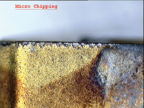
4. Chipping of insert cutting edges originates from mechanical instability often created by non-rigid setups, bad bearings or worn spindles, hard spots in work materials or an interrupted cut. Ensuring proper machine tool setup, minimizing deflection, using honed inserts, controlling built-up edge, and employing tougher insert grades and/or stronger cutting-edge geometries will deter chipping.
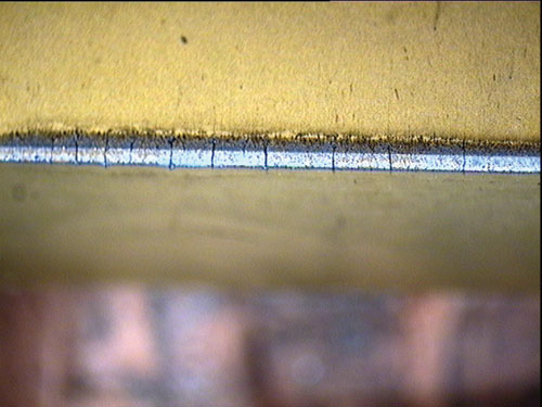
5. Thermal mechanical insert failure comes from a combination of rapid temperature fluctuations and mechanical shock. Stress cracks form along the insert edge, eventually causing sections of the insert’s carbide to pull out and appear to be chipping. A signs of thermal mechanical failure is multiple cracks perpendicular to the cutting edge. It is important to identify this failure mode before chipping begins. To prevent thermal mechanical failure, apply coolant correctly, or better yet, remove it from the process completely, employing a more shock-resistant grade and using a heat-reducing geometry.
6. Edge deformation arises from excessive heat combined with mechanical loading, as is often the case with mold machining. High heat can occur at high speeds and feeds or when machining hard steels, work-hardened surfaces and high-temperature alloys. This causes the carbide binder or cobalt in the insert to soften. Edge deformation is controllable by using a more wear-resistant insert grade with lower binder content, reducing speeds and feeds and employing a force-reducing insert geometry.
7. Notching becomes noticeable when notches and chips appear in the depth-of-cut area on an insert. To prevent notching, vary the depth-of-cut when using multiple passes; use a tool with a larger lead angle; increase cutting speeds when machining high-temperature alloys; reduce feedrates; carefully increase the hone in the depth-of-cut area; and, prevent build-up, especially in stainless steel and high-temperature alloys.
8. Mechanical fracturing of an insert occurs when imposed force overcomes the inherent strength of the insert cutting edge. Any of the seven other failure modes can contribute to fracturing. Avoid mechanical fracturing by correcting for all other failure modes besides normal flank wear. Using a more shock-resistant grade, selecting a stronger insert geometry, using a thicker insert, reducing feedrates and/or depth-of- cut, verifying setup rigidity and checking the workpiece for hard inclusions or difficult entry are all effective corrective actions.
Cutter Grades, Geometries, Materials and Sizes
Most cutting tool manufacturers develop cutting tool grades and geometries for specific materials. In mold machining, those materials are typically P20 steels, CPMV 10 and powdered metals. It is critical to select the right grades and geometries according to the particular material being machined to avoid premature tool failures. Additionally, matching cutting tool to material increases performance and predictability, which results in fewer tool changes, less rejects and less reworking.
If a material is 52 Rc or softer, general-purpose solid carbide tools work well. For materials harder than that, solid carbide end mills with different geometries and coatings such as aluminum titanium nitrate designed for extremely hard materials should be used. Plus, for solid carbide tooling, there are special blends of coatings unique to individual tooling manufacturers. For indexable insert cutters, insert geometries and coatings for hard milling will work for most extremely hard powder metals. And the different insert grades and chip grooves available on today’s indexable insert cutters make it possible to optimize machining harder mold materials.
Once cutter types are determined, proper cutter radii sizes must be selected. Cutter radii must be smaller than inside mold corner radii. If the radius of a tool matches that of a mold’s corner radii, what is known as a hard stop will occur; as opposed to the cutter flowing smoothly through the radius. For finishing, smaller diameter solid carbide cutters are recommended. And today solid carbide high-feed cutters are also available.
The same radii principle also holds true for roughing operations—using cutter radii smaller than those of the workpiece. And while this leaves more material in corners, it helps maintain consistent, even cutter load for all the subsequent semi finishing and finishing operations.
Just as critical as cutter radii is cutter rigidity, and cutter draft angles/tapers play a key role in this. Most cutters are either relief neck or tapered neck styles. Relief neck tools provide a smaller diameter than the flute size above the flutes and below the cutter’s shank diameter. With tapered neck style tools, there is the cutting diameter, then a relief area that is smaller above that, and then a taper up to the shank diameter. Most long-reach cutters incorporate tapered neck designs.
Less draft angle means more rigidity in the tool. But, draft is needed to avoid rubbing against mold cavity sidewalls. To choose the most rigid cutter, mold cavity drafts must be taken into consideration. Cutting tool drafts should never match or exceed mold drafts. For instance if a mold cavity has a 3-degree draft on all its sidewalls, tools with drafts up to 2.5 degrees on their relief can be used.
Coolant
As far as the use of coolant is concerned in mold machining, most of today’s advanced cutter designs and geometries perform at their optimum when run dry. The exception is running with oil mist, but doing so at all times. For hard milling, the rule is absolutely no coolant at all, unless oil mist is available.
Holders
When it comes to toolholding, most cutting tool companies recommend vibration-dampening holders for mold machining and for use with today’s advanced cutters. The best tool in a sub-par holder will fail to achieve optimum performance and tool life, while advanced high-performance holders can potentially double tool life.
Vibration control is critical, especially with long tool gage lengths and in high-feed milling, rough machining applications. The key is that these vibration-dampening holders are designed to reduce harmonics and vibrations generated by the cutting process.
Cutter Paths and Programming
Mold machining cutter paths should be optimized through proper programming to avoid placing unrealistic demands on cutting tools. For example, when machining a mold and the toolpath initiates a corner, a smooth transition must be programmed for changing direction to prevent creating a large angle of engagement, which can overload the cutting tool. A good rule of thumb is to program an arc that is larger than the cutting tool’s radii. So, if a 2-inch diameter cutter is used, the program should not encounter 1-inch radii, but instead use a smoothing radius that is larger.
Programming proper arcs can be a challenge, and if not done properly, can lead to erratic toolpaths. Several current software packages can aid in accurately programming the cutter paths for this technique. Also, a knowledgeable programmer with an understanding of the arc of contact principle is helpful. The key is to avoid machine stop and start scenarios in the toolpath. Any amount of machine hesitation when changing directions generates heat that transfers to the tool. Heat can destroy a tool’s cutting edge and coating, and must be evacuated from the cut zone within the chips.
Summary
By gaining a better understanding of today’s milling techniques and tooling technologies as well as the various failure modes and failure analysis skills, mold manufacturers can experience increased productivity, reduced cycle times, better tool life and tool life consistency, improved part tolerance and appearance, superior mold surface finishes, and less wear and tear on equipment.


Related Content

How to Overcome Cutting Tool Vibration
Advanced indexable milling cutting tool design provides secure, predictable machining, increased metal removal rates, reduced cycle times and fast changeovers.
Read More
6 Ways to Optimize High-Feed Milling
High-feed milling can significantly outweigh potential reliability challenges. Consider these six strategies in order to make high-feed milling successful for your business.
Read More
How to Optimize Mold Finishing
Circle segment technology requires fewer tool paths, improving surface quality and increasing cutting tool life.
Read More
Ten Things You Need to Know about Circle Segment Milling
Considerations for evaluating if circle segment end mills or conical barrel cutters are right for your mold machining applications.
Read MoreRead Next

6 Ways to Optimize High-Feed Milling
High-feed milling can significantly outweigh potential reliability challenges. Consider these six strategies in order to make high-feed milling successful for your business.
Read More
How to Use Continuing Education to Remain Competitive in Moldmaking
Continued training helps moldmakers make tooling decisions and properly use the latest cutting tool to efficiently machine high-quality molds.
Read More
How to Use Strategic Planning Tools, Data to Manage the Human Side of Business
Q&A with Marion Wells, MMT EAB member and founder of Human Asset Management.
Read More