
Simplify Mold Design with Robotic Automation
Six-axis jointed robots can offer significant cost savings during mold design and manufacture, as well as during production.


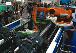
A robot mounted to an injection molding machine.
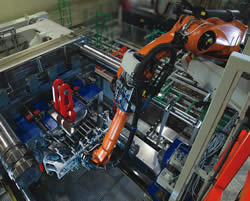
Close-up of a robot extracting a bumper from a large IMM using a shelf mount robot on the fixed platen. This appears to have low ceiling clearance. Images courtesy of KUKA Robotics.
Manufacturers have many factors to consider when designing equipment to manufacture products in the plastics industry. Six-axis jointed robots can offer significant cost savings during mold design and manufacture, as well as during production.
Using a robot to machine cavities in the part enables moldmakers to simplify mold design with fewer moving parts, like retractable cores. Removing core features from the molded part also eliminates obstacles to material flow, which further simplifies design. Machining core features instead of molding enables easy product changes, requiring no costly mold retrofits.


The high rigidity and flexibility of the jointed robot arm enables high pull forces that sometimes can replace ejector mechanisms in the mold. Simpler design lowers the cost of the mold manufacture and reduces time-to-market.
In addition, robots have the capability to do insert molding applications. Robots can place inserts very accurately into the mold. Compared to a manual operation, it is much more efficient since the machine can be run in full-automatic mode. When placing the inserts manually, the operator needs to stop the machine, disable guarding, place inserts and re-enable the safeties, losing valuable production time.
Factors to Consider when Designing Robotic Automation
First the designer needs to understand the process and what needs to be accomplished with the automation. Will you use the robot for part removal, inserts, machining, marking, weighing, machine vision inspection, cutting of sprues, trimming of parts or assembly? Are there other process requirements like cooling time or cleanliness? These items will make a big difference to the cell layout.
Several different layout concepts should be evaluated. Consider what space is available in the plant. There are shelf-mounted robots and overhead mounted robots that can save quite a bit of floor space. Since floor space is at a premium, manufacturers usually look for space-saving ideas. These concept layouts focus more on understanding the process concepts like product flow.
After determining an approximate cell layout, consider robot selection. When selecting a robot model, determine the reach and payload needed for the application. A key factor in developing a successful robotic system is to be sure the payload is within limits of the robot selected. It is important to consider center of gravity and moment of inertia. Consider what process forces and torques might be required, like insert press force or part removal force. Cycle time can also be an important factor, along with the accuracy that is required for the process operations in your work cell. Machining holes or performing assembly may require a higher accuracy than just taking a part out of a mold. Robot selection is a key step for success of the system, so asking the help of a robotics expert may be needed.
After the robot selection and reach evaluation, designers need to consider the end-of-arm tooling. For end-of-arm tooling, determine how the part can be held—with either a vacuum or mechanical gripper, or a combination of both. In addition, sprues may need to be held in place while trimming, so that pieces won’t be dropped. An important factor in end-of-arm tooling is part location—especially for machining or assembly operations—to be sure the part is positioned accurately.
If placing inserts, manufacturers should consider how to hold the insert piece while also removing the molded part. This reduces cycle time. By properly analyzing the process, robotics will allow you to grab the complete part out of the mold, reposition and place the insert for the next part—all without exiting the molding machine. The challenge to this design problem is determining how to hold the insert due to space considerations.
Cell safety is a consideration that should be prominent through the entire design process. Important considerations are fencing to protect operators from the robotic system, along with placement of hard stops, which prevent the robot from going outside of the designated area.
Controls Make a Difference
Controls also are an important consideration when determining how the robot will integrate with the injection molding machine, plant control system or production controller/monitoring system. For example, some robots can be integrated with molding machines thanks to standard interfaces like SPI AN-116 and AN-146. Support for many industrial communication protocols facilitates communication with other systems.
Some advantages to PC-based control technology are the ability to have the Windows interface and Plastics Graphical User Interface software. Standard HMI (human machine interface) products are available to help designers create custom user interfaces for the robot. This feature allows the HMI to connect to and command other pieces of equipment using OPC Technology—enabling communication over a standard Ethernet network. The HMI can pull status displays or control functions all together on one display at the robot. The interfaces can include text and graphics to describe the process and can even animate displays.
Other packages also can be used on the robot to extend its capabilities. Soft PLC software (embedded software technology inside a controller CPU) enables the controller to double task and eliminate the need for a dedicated PLC (programmable logic controller) to control the cell. This can be programmed with standard ladder logic like any other PLC or with any IEC1131 method. A SoftPLC is very useful when the cell requires more complex control than normal robot programming offers.
New Software Programs Create Efficiencies
Robot manufacturers also offer new software that allows designers to create a work cell simulation that is an excellent tool to use for the design process. This simulation software is a 3-D virtual environment that allows users to verify reach, clearances and the process concept. Other benefits are creation of paths, cycle time estimates and offline programming.
Other software allows end users to evaluate the robot’s payload capacity to verify if the end-of-arm tooling and robot are well matched. This software determines if the center of gravity and moment of inertia are good for the particular robot selected and can also be used to identify the robot that would be best suited for an application.
Summary
Six-axis robotic automation is well established as a cost-saving technology for manufacturing. However, its application in the plastics industry is fairly new. Considering robotics as part of the complete solution for manufacture of a part, instead of an afterthought, can generate significant savings for the system. Incorporating material removal capabilities in a cell that uses multiple molds can magnify savings on mold design and manufacturing for all the molds that may be used in the cell. As with any technology, there is a learning curve, but the rewards of adopting new technology are lucrative.
For information on work cell safety standards developed by the Robotic Industries Association visit www.roboticsonline.com.
| Comparison of Jointed Arm Robot Versus Linear/Gantry Systems | |
| Below is a chart that shows the differences between implementing a six-axis robot and a linear/gantry unit to do part extraction. | |
| Jointed Arm Robot: Stiffness
Shelf-mounted robots can demold parts either with force (forced removal from negative mold) or delicately (demolding from core). Despite the extended position of the shelf-mounted robot during demolding, it retains its extreme stiffness. The flexibility of the gripper allows the parts to be twisted freely out of the (sometimes enormous) undercutting of the injection mold. |
Linear/Gantry: Stiffness
By observing a linear robot in the lowest position (telescope extended), it quickly becomes apparent that the stiffness is greatly reduced due to the long lever arm. Due to this weak point additional mechanical support is needed. For this the motion is restricted on linear motion. |
| Jointed Arm Robot: Mold Costs
Complex parts with undercutting can be extracted from the negative injection mold without the need for additional, cumbersome gripper props. As for the injection molds themselves, it is possible, at least partially, to dispense with ejectors, core pullers and side loaders, thus making the molds considerably cheaper. Potential savings on molds. |
Linear/Gantry Systems: Mold Costs
The linear/gantry systems are only of limited use for removing complex parts from negative molds; in most cases, the articles to be demolded are ejected. Complicated and expensive molds with side loaders, core pullers and ejectors are required, as are additional props on the extractor gripper. Expensive molds with additional functions. |
| Jointed Arm Robot: Large Volume Parts
Using toolchanger carriages mounted on either side, it is possible to equip injection molding machines with tools/molds that are actually larger than the gap between the two beams. Because of its six-dimensional freedom of movement, the shelf-mounted robot positioned on top of the machine is able to demold these bulky parts. For robot no problem. |
Linear/Gantry: Large Volume Parts
External axes are required for the removal of large-volume parts using linear handling devices. In addition, a spacer is required on the fixed mold clamping plate in order to demold the large-volume parts over the upper machine beams. Additional axes required: |
| Jointed Arm Robot: Cleanliness/Quality
Enclosed guide mechanisms only very rarely cause problems with dirt. |
Linear/Gantry: Cleanliness/Quality
Because of the exposed tracks, there is the danger of lubricating oil from the traversing axes dripping on the demolded plastic parts. This causes major problems and loss of quality in the case of subsequent painting. It is often necessary to repaint the parts. |


Related Content

Achieving Flexible Capacity with Automation
This high-mix, low-volume manufacturer embarked on a year and a half program to introduce robotics to its manufacturing process.
Read More
How to Use Ultra-Precision Micro Tools, Molding and Automation to Unlock High-Volume Medical Device Miniaturization
Five key areas where a molder/mold builder applies tight-tolerance tooling and advanced molding solutions to enable high-volume production of micro-molded medical parts.
Read More
Adopting AI: A Pragmatic Approach to Your AI Journey
How mold builders can start AI efforts without expensive system overhauls or major changes.
Read More
What Is Scientific Maintenance? Part 1
How to create a scientific maintenance plan based on a toolroom’s current data collection and usage.
Read MoreRead Next

Standardize Before You Automate
After standardization, automation will create the largest increase in profits that any one area can produce.
Read More
How to Use Strategic Planning Tools, Data to Manage the Human Side of Business
Q&A with Marion Wells, MMT EAB member and founder of Human Asset Management.
Read More
How to Use Continuing Education to Remain Competitive in Moldmaking
Continued training helps moldmakers make tooling decisions and properly use the latest cutting tool to efficiently machine high-quality molds.
Read More