
Overcoming the Obstacles to Interoperability
Technical know-how and the right software can provide data transfer with a very high success rate.


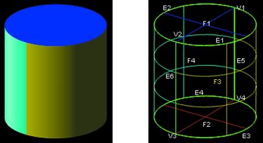
Figure 1a (left): 3-D object topologically represented. Figure 1b (right): 3-D object geometrically represented.
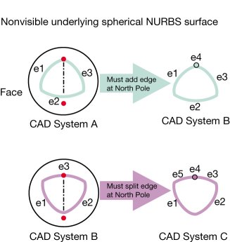
Figure 3: Geometrically the same face can be topologically represented in different ways.
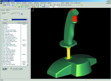
Figure 4: Healing software guides the user through different categories of errors by highlighting problem areas and removing unrelated screen clutter.
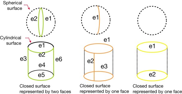
Figure 2: Closed surfaces represented differently among CAD systems.
Today's popular CAD systems share a common technical foundation in the way solid (and surface quilt) models are internally described and represented. Of course, the specifics differ from one system to another, which gives rise to the very challenges that face interoperability.
Modern modeling systems define a 3-D object by its topology and geometry. Topology describes connectivity of the object boundary (Boundary Representation or B-Rep), which is defined by vertices, edges and faces. A face is itself a subset of a limited region in space defined by underlying surface geometry. Geometry describes the shape of the object, which is defined by points, curves and surfaces. Most commonly, curves and surfaces are described using Non-Uniform Rational B-Splines, or NURBS. A 3-D object is defined fully only when both topology and geometry are complete and coherent. For example, the 3-D object in Figures 1a and 1b is topologically represented by four faces, six edges and four vertices, and geometrically represented by two planes, two cylinders, four arcs, two lines and four points.


Obstacles to Interoperability
Even though the underlying modeling technology is similar among various CAD systems, there are a number of significant differences in how 3-D objects are defined. CAD systems must select various tolerances that best suit their mathematical algorithms for generating generally shaped surfaces, surface-surface intersection curves and positions in space. This must be done because computers are machines with limited floating-point precision.
For example, an IEEE sixty-four-bit floating-point (real number) representation gives fifteen digits of precision. In addition, many mathematical algorithms are numerical and iterative in nature, for which exact solutions simply don't exist. Therefore, appropriate tolerances must be used as stopping criteria to decide when a numerical solution is "good enough." This works fine within each CAD system as long as the selected modeling tolerances are smaller than those used in the manufacturing processes. However, if a part needs to be exchanged between CAD system A and B, then the differences in modeling tolerances come into play and may cause geometric inconsistencies, affecting the translation success rate.
The following are examples of problems that can arise during translation between two CAD systems due to different tolerances:
- A curve start and end points are not coincident with edge terminal vertices to within the receiving CAD system tolerance.
- A curve representing an edge between two faces does not lie on both surfaces to within the receiving CAD system tolerance.
- An edge may be considered too small in the receiving system and should be represented by a vertex instead.
- A face may be considered too small in the receiving system and should be represented by an edge or a vertex instead.
A different set of translation problems can arise due to topological differences. For example, Figure 2 shows closed surfaces represented differently among CAD systems. Another example involves surfaces with degenerate boundaries (see Figure 3). By definition, all NURBS surfaces are four-sided. Degenerate surface boundaries arise when a NURBS surface is used to represent a sphere (two degenerate boundaries: north and south poles) or a triangular-shaped patch (one degenerate boundary), for example. Topology may have to be modified to be compatible with the receiving system. This really is a topology that is a result of the limitations in the NURBS technology, so it can be called an artifact topology.
Meeting the Challenge
It is clear that CAD data translation requires a high level of knowledge and experience in both modeling technology and the specifics of the sending and receiving CAD systems. Reliable data translation cannot be accomplished by a casual development effort. In addition to the technical know-how, the maturity and comprehensive exposure to a wide range of large models of different industries is a trademark of good software.
Data Exchange Kernel
To be able to approach CAD data translation well, the product you select needs to have robust kernel technology that allows the transfer of data based on known rules and tolerances of each specific CAD system. CADporter is translation software that has the underlying Data Exchange Kernel (DEK), which has a knowledge base of eighteen years of experience and a built-in automatic healing technology that adapts using known rules based on the sending and receiving CAD system.
Real user models - directly from automotive, consumer electronics and aerospace CAD users - act as the test suite for this translation software system, which always is being updated with new models so that DEK is constantly evolving and getting more robust.
When a part is to be translated from system A to B, DEK will perform the following steps:
- Determine appropriate tolerances that should be used based on both systems A and B.
- Perform appropriate geometric and topological checks, which are specifically customized based on both systems A and B.
- Autoheal problem areas in appropriate order. The autohealing performed by DEK includes, but is not limited to, the following:
- Eliminating gaps that result from modeling tolerance differences
- Reintersecting edges to derive geometry at a tighter tolerance when needed
- Splitting edges that contain curve discontinuities (cusps). Basically, these are curves that are not geometrically smooth as determined by the receiving system.
- Splitting faces that contain surface discontinuities (creases) (basically, these are surfaces that not geometrically smooth as determined by the receiving system)
- Eliminating short edges and sliver faces
- Adding/removing edges at degenerate surface boundaries
There are two cases where DEK's automatic healing may not result in a 100 percent translation success rate:
1. DEK has the knowledge of the required changes, but they are deemed too drastic to make automatically without the user's explicit acknowledgement. Of course, user-defined switches can be set to apply such changes automatically.
2. The modeling intent is not clear such that it can be made automatically. For this case, an interactive graphics tool was developed that allows the end user to review and apply the appropriate healing technique.
Interactive Graphics Tool
To solve these very difficult problems, an intuitive, interactive graphics tool is needed to guide the end user into fixing and healing CAD models. One such interactive graphics tool (CADdoctor) is built on the same DEK foundation as the translation software. The major advantage of using this interactive graphics tool is the ability for the end user to categorize and visualize geometrical and topological inconsistencies graphically, to be able to learn from them, and to work to avoid them in the future.
The software guides the user through different categories of errors by highlighting problem areas and removing unrelated screen clutter (see Figure 4). Then it proposes various fixes that can be viewed and accepted or rejected based on user requirements (see Figure 5).
Furthermore, model construction functions also are available - such as filling holes (models with missing faces), refitting curves and surfaces, retrimming surfaces, and automatically stitching free edges, which comes in handy when importing IGES files.
One particularly unique function allows the user to fix edges that are off the face geometry by locally deforming the face geometry along the edges. The face geometry is treated as an elastic deformable thin plate that is stiff on the interior (to restrict interior shape changes) and flexible along the edges.
Summary
Although the obstacles to interoperability are many, technical know-how and the right software can provide data transfer with a very high success rate. Due to the complex and dynamic nature of CAD software today, the best tools will combine ease of use, technical depth and long experience. In addition, specialized healing tools can provide the user with automatic and semiautomatic functions for addressing geometry and topological inconsistencies.


Related Content

How to Fix Predicted Warpage Before It Happens with Windage and CAD Model Morphing
Applying windage and model-morphing techniques saved toolmaker/molder Sturgis Molded Products the time, cost, headaches of multiple part/mold design iteration loops, cumbersome cooling fixtures, and long molding cycles.
Read More
Tips for Tackling Mold Design, Machining, Cutting Tool and Wear Challenges
Tips for tasks ranging from reducing risk in part design and taking advantage of five-axis machining to refining cutting tool performance and reducing wear with guiding and centering systems.
Read More
Three Good Reasons to Switch from Three- to Five-Axis Machining in Moldmaking
Five-axis machining technology is a great tool in the moldmaker toolbox.
Read More
Mold Design Review: The Complete Checklist
Gerardo (Jerry) Miranda III, former global tooling manager for Oakley sunglasses, reshares his complete mold design checklist, an essential part of the product time and cost-to-market process.
Read MoreRead Next

CAD Interoperability: Its Costs to Mold Design and Mfg
An industry survey reveals some real data on how CAD interoperability is affecting mold shops.
Read More
Overcoming Pain Points in Moldmaking with AI
Shops that embrace AI as a tool, not a threat, can enhance efficiency, preserve expertise, and attract tech-savvy talent.
Read More
Reasons to Use Fiber Lasers for Mold Cleaning
Fiber lasers offer a simplicity, speed, control and portability, minimizing mold cleaning risks.
Read More