Integrating Electrode Production
How CAD/CAM can help make the design, machining and inspection of electrodes completely integrated.
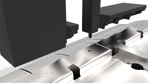
An integrated system for the design, machining and inspection of electrodes.

: The production of electrodes is a key stage in the manufacture of many types of tooling, including injection molds, so the availability of a faster, more automated method for their development will increase efficiency and reduce leadtimes across a number of industries. Currently, the design, machining, inspection and use of electrodes are undertaken as separate activities. Closer integration of these key stages into a single workflow, based on a single data file, would offer a faster, more reliable and more productive process.


The production of electrodes is a key stage in the manufacture of many types of tooling, including injection molds, so the availability of a faster, more automated method for their development will increase efficiency and reduce leadtimes across a number of industries. Here is where CAD/CAM comes into play.
Can you imagine a CAD/CAM file format that enables the design, machining and inspection of electrodes to be completely integrated? Well, if it exists that file would need to contain all of the information developed during each electrode project—including not only the electrode design, but also the machining and inspection information, as well as the setup sheets and scripts. Then all of this required information would need to be in a single file to simplify data management as well as increase overall efficiency.


Here is what to look for in this type of a CAD/CAM solution for electrode production integration:
The first step in creating the file would come during the initial design stage of electrodes. The design software would allow users to quickly and easily define the region where the electrode will be used; extract the shape needed to produce the required feature in the part; and then, edit the design to provide clearance from the main surface of the tool and to blend it into the blank size needed to fix the electrode into its holder.
Design software usually includes analysis tools to check that the draft angles and minimum radii used in the design will not cause downstream problems, but on top of that would be the ability to simulate the action of the electrode on the computer, which ensures it will operate as expected on the EDM equipment.
To speed the design process further, catalogs of blanks and holders from leading suppliers should be included in the software, but users should also be able to add their own standard sizes to these databases.
Once the design has been finalized, the information in the data file would need to be extended to include the spark gaps necessary to provide the offsets required in the machining software that will be used to cut the roughing and finishing electrodes. Inspection points would also have to be added, so that the measurement of the machined electrode could be automated to a large extent. In addition, setup sheets for the electrode’s manufacture and use should be produced automatically—either to a standard format or to a user-defined template.
Companies that produce multiple electrodes of similar sizes from the same material will find it worthwhile to develop templates within their CAM programming software to machine them in a standardized way. Your CAD software should automatically color-code burn, clearance and blank faces of the electrode during the design stage, so that they can be recognized within the machining software. The size of the material block and the spark gaps for the electrode family should also be incorporated into the project data file and applied to the toolpaths automatically. Once the templates have been created, generating the machining toolpaths should become a fully-automated process.
This automation will save considerable time for the user; however, when machining a large number of electrodes, it is inefficient to wait for toolpaths to be calculated on each individual project. To overcome this problem, applying batch processing to multiple projects is necessary. With this approach, processing the toolpaths starts as soon as the first project is loaded.
Subsequent projects displayed in a list with calculations beginning on the next item in the list automatically is ideal. If the calculations for a particular electrode cannot be completed—for example, if the system detects a collision—the problem should be recorded and the software should move on to the next item automatically. Thus, a long series of calculations can be left to run overnight if necessary.
Specifying the inspection points within the file during electrode design means that the probe path for the inspection and the production of the inspection report will be automated—including undertaking a best-fit analysis of the machined electrode. The results of the inspection need to be able to be added to the project data file for quality control records.
Scripts are the EDM equivalent to CAM programs for machine tools. They provide an automated process for the programming of the machine, instead of users having to program manually from a setup sheet. The automated process is much easier and quicker, especially when a number of electrodes are being used on the same component. In addition, the direct link removes the human error that could always be possible with manual programming.
The automated generation of setup sheets would need to be possible for both the machining and application of the electrodes to ensure that all the data needed at each stage is readily available. A documentation pack, including the GA and detail sheets, would need to be generated in various formats—such as drawings, HTML files or Microsoft Excel spread sheets. All these options are important to allow easy communications between the various people involved in the design, manufacture and use of the electrodes.


Related Content

How to Map Mold Water Circuits
Prevent mold damage and maintain consistent part quality by using a mold mapping system that ensures consistent turbulent flow.
Read More
Questions and Considerations Before Sending Your Mold Out for Service
Communication is essential for proper polishing, hot runner manifold cleaning, mold repair, laser engraving and laser welding services.
Read More
5 Hot Runner Tips for Moldmakers and Molders
Best practices for initial hot runner tryouts and effective preventive maintenance.
Read More
Four Micro Tooling Considerations
Issues involving gating, ejection, mold splits and direction of pull are of special concern when it comes to micro tooling.
Read MoreRead Next

Software Advances Push Limits of Speed and Quality
Software for moldmaking continues to evolve as sophisticated features and capabilities are introduced, enabling mold manufacturers to produce the highest quality work in the most compressed leadtimes to date.
Read More
Reasons to Use Fiber Lasers for Mold Cleaning
Fiber lasers offer a simplicity, speed, control and portability, minimizing mold cleaning risks.
Read More
How to Use Continuing Education to Remain Competitive in Moldmaking
Continued training helps moldmakers make tooling decisions and properly use the latest cutting tool to efficiently machine high-quality molds.
Read More