
Tooling Up for Challenging Cuts
To maximize quality and repeatability, you need the right cutting tools, especially in challenging applications. Here’s a guide for selecting tools for high-speed tool paths, tight areas, straight walls and graphite cutting.
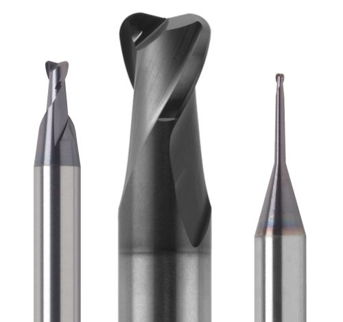
Toroidal tools like these are appropriate for machining tight areas. Images courtesy of RobbJack Corp.
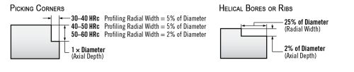
This chart shows the recommended widths and depths for machining with toroidal tools.
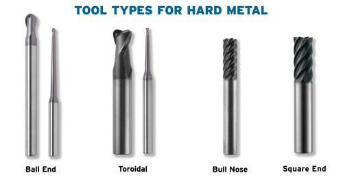
A variety of tool types are available for cutting hard materials, including (left to right) ball-end, toroidal, bull-nose and square-end tools.
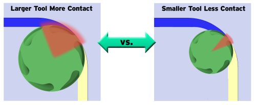
This diagram illustrates the increased surface area created by a larger cutting tool vs. a smaller cutting tool.
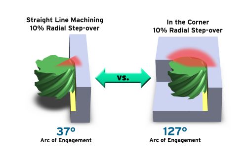
In straight-wall machining there is a 37-degree arc of engagement, while a traditional corner cut produces a 127-degree arc of engagement.
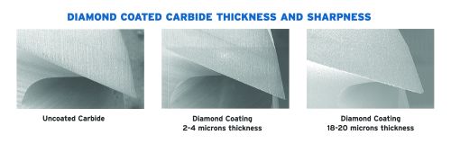
These magnifications show cutting tool edges that are (left to right) uncoated, coated with a 2-4-micron-thick diamond coating and coated with an 18-20-micron-thick diamond coating.


Determining the most appropriate cutting tool is essential when looking for quality and repeatability in each job, especially when you are faced with challenging conditions like high-speed tool paths, tight areas, straight walls and graphite cutting. Following are guidelines for selecting the best tools for these types of applications.
High-Speed Tool Paths
Today’s CAD/CAM systems offer machinists extraordinary precision by controlling the arc of engagement in high-speed, trochoidal tool paths. (A trochoidal tool path is the curved path of a fixed point on a circle that rolls along a straight line.) The amount of engagement does not increase, even when the designer enters a corner or other complex geometry. Modern, small-diameter cutting tools have been designed to take advantage of this technological advance. Smaller tools are less expensive than larger-diameter tools and oftentimes are able to remove more material per minute using high-speed tool paths. This is because a larger-diameter tool creates greater surface contact, requiring it to slow down to more conventional feed rates. As a result, a smaller tool offers a higher metal removal rate.


However, with these smaller tools, the designer still needs to make sure that the tool and tool coatings are designed not only for trochoidal cutting, but also for the material being cut. Today’s high-performance tools have application-specific geometries that are appropriate for the material being cut as well as the cutting technique being employed. For example, a six-flute tool can cut a full slot in 54-HRc H13 steel following optimized tool paths. A ½-inch-diameter tool can create a 1-inch-wide slot. Trying to use a ½-inch-wide tool to create a ½-inch-wide slot would create too much surface contact, and the tool would fail immediately. A good rule of thumb is to use a tool about half the size of the tightest area. In this example, the tightest area is the 1-inch slot, so the ½-inch-diameter tool is the largest tool that should be used. When the tool radius is smaller than the tightest area of the part, there is room for the tool to move around, and the engagement angle is minimized. This means a tool with more cutting edges and faster feed rates can be used.
Machine rigidity also helps dictate the size of the cutter that can be used. In 40-taper machines, for example, the diameter of the tool is typically less than ½ inch. Larger-diameter tools generate more force than the machine can handle, resulting in chatter, deflection, poor finish and decreased tool life.
In addition, when the tool is half the size of the tightest area, the angle of engagement can stay low and not increase. For example, if you program a part with a 10-percent stepover, the angle of engagement is 37 degrees. With older, traditional tool paths, this engagement angle would increase to 127 degrees every time the tool changes direction. In newer, high-speed tools paths, the tool literally “sounds” the same in corners as it does in straight-line cuts. Sound is a good way to check on the optimization of the tool paths. A tool that sounds the same during all the cutting is not experiencing spikes in heat and shock. If the tool squeals every time it changes direction or hits a corner, it is an indication that you may want to decrease the cutter diameter of the tool to reduce the engagement angle. When the cut sound is consistent, the tool is experiencing constant pressures that are not fluctuating as the part geometry varies. This is because the angle of engagement remains constant.
Tight Areas
Toroidal tools are the best choice for cutting tight areas such as helical bores and ribs, or when the cutter diameter is close to the radius of the part. The tool’s robust, toroidal shape creates a chip-thinning effect that allows it to cut at faster feed rates. In addition, its radius is smaller than a traditional ball-end tool, so you can increase stepovers and still maintain flat floors without the large cusps typically generated by ball-end tools.
Toroidal tools are well-suited for helical bores and ribs because these applications naturally create a lot of surface contact with the cutter. Using a two-flute cutter with a toroidal shape will minimize surface contact, heat and deflection during cutting. In these two applications, the toroidal tool is usually encapsulated in the cut, therefore, the maximum radial stepover is 25 percent of tool diameter, and the maximum Z depth per pass is 2 percent of tool diameter. When the tool is helically entering the part, or in helical bores, the helical entry angle is 2 to 3 degrees until you get to the 2-percent Z depth.
When the tool is not encapsulated in the cut, for example, when it is picking out a corner of a part or cleaning up features, material hardness determines the radial stepover. In 30- to 50-HRc material, the maximum radial stepover is 5 percent of tool diameter. In materials harder than 50 HRc, there is a 2-percent maximum radial stepover and a maximum Z depth of the tool diameter per pass.
Straight Walls
Bull-nose cutters work best for cutting in wide-open areas with flat floors or straight walls. Tools with four to six flutes, in particular, can excel when profiling the outside shape with straight walls or very wide-open areas. The higher number of flutes allows for faster feed rates, although the programmer still must minimize the amount of contact with the cutter and use light radial-width cuts. Operations on less-rigid machines benefit from using smaller-diameter tools, as they reduce the amount of surface contact.
Multi-fluted bull-nose cutters are applied the same way as toroidal tools, and use the same stepovers and depths of cut. They can cut slots in hardened materials using trochoidal tool paths or new tool paths that control the cutter engagement angle. As explained earlier, it is important to make sure the tool is about 50 percent of the slot width to allow for enough movement and to ensure that the angle of engagement does not increase and generate too much heat.
Graphite Cutting
The abrasiveness associated with cutting graphite quickly wears out standard carbide tools, and then the worn tool will not accurately cut the necessary complex geometries. Cutter path and technique are not as critical in graphite cutting applications, so it is usually the electrode shape that dictates the type of cutter. Diamond-coated tools are widely used in these applications because they offer added wear resistance. Diamond is grown on the carbide tool, creating a very hard, wear-resistant layer that greatly extends tool life. The life of a diamond-coated tool ranges from 10- to 30-times longer than that of uncoated carbide cutters.
For example, a ¼-inch–diameter, uncoated carbide, ball-end tool typically can cut a 6-by-6-inch complex graphite electrode for about four hours before its razor-sharp, detailed features start flaking at the edges. A diamond-coated tool can last more than 98 hours without any flaking of the edges.
Some graphite shapes such as thin ribs, sharp geometries and small part sizes specifically require tools with very sharp cutting edges. Even a 2-to-3-micron-thick diamond coating can improve tool life and maintain the sharp edge in such applications. Because this thinner diamond is less expensive, it is ideal for lower-production applications that don’t require tool life to be as long as that provided by the typical 18-micron thickness.
Technology such as this means moldmakers with smaller production quantities that are looking for less-expensive tools don’t have to sacrifice tool life for lower cost. They can still get the advantages of true-diamond-coated carbide tools, but also take advantage of the fact that thinner diamond coatings will satisfy the requirements of their particular applications. Diamond coatings today are available in thicknesses ranging from 2 to 25 microns.
The best cutting tool for a particular application should not only be determined by the material being cut, but by the type of cutting and milling technique as well. By optimizing the cutting tool, speeds and feeds, and programming techniques, parts can be made faster and with lower operating costs.


Related Content

Precision Meets Innovation at IMTS 2024
After attending IMTS, it's clear that the integration of advanced technologies is ready to enhance precision, efficiency and automation in mold manufacturing processes. It’s a massive event, so here’s a glimpse of what the MMT team experienced firsthand.
Read More
How to Overcome Cutting Tool Vibration
Advanced indexable milling cutting tool design provides secure, predictable machining, increased metal removal rates, reduced cycle times and fast changeovers.
Read More
6 Ways to Optimize High-Feed Milling
High-feed milling can significantly outweigh potential reliability challenges. Consider these six strategies in order to make high-feed milling successful for your business.
Read More
How to Machine Aluminum Molds to Enhance Efficiency and Quality
Ways to optimize the machining process to fully leverage the benefits of an aluminum mold.
Read MoreRead Next

Choosing the Right Cutting Tool for Pre-Hard Materials
There are four common tool types to consider for cutting pre-hard materials: ball-end, toroidal, multi-fluted bull-nose and square-end.
Read More
How to Use Continuing Education to Remain Competitive in Moldmaking
Continued training helps moldmakers make tooling decisions and properly use the latest cutting tool to efficiently machine high-quality molds.
Read More
How to Use Strategic Planning Tools, Data to Manage the Human Side of Business
Q&A with Marion Wells, MMT EAB member and founder of Human Asset Management.
Read More