
New Tool Concepts for Machining Dies and Molds
The development and introduction of new insert and tool geometries for machining dies, molds and housing is an ongoing process - improving performance, tool life, surface quality and economy.


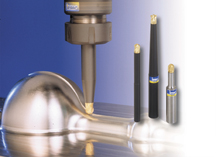
Figure 5: Endmills with interchangeable heads for various milling and profiling operations.
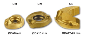
Figure 12: Helical cutting-edge inserts for ballnose tools with screw clamping.

Figure 2A and 2B: Injection mold for the electronic industry and a forging die for turbine blades.
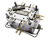
Figure 3: A mounted mold for the electronic industry.
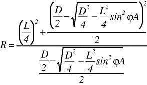
Figure 7b: The equation for the helical edge concept.3
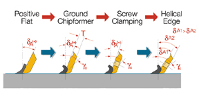
Figure 6: Basic insert geometry for face-, shoulder- and slot-milling.
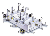
Figure 4: Various milling and drilling tool families for dies and molds.
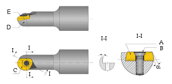
Figure 13: Ballnose endmill design for small diameter tools and high-speed milling.
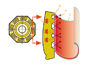
Figure 11: Groove-type chipformer for improved tool life.

Figure 7a: The unique helical cutting edge concept.3
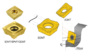
Figure 9: Square inserts - four heli-cutting edges for 90' shouldering, facing and slotting.
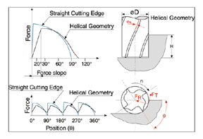
Figure 8: Cutting forces on helical and straight cutting-edge endmills.
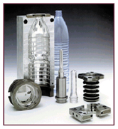
Figure 1: The main parts of a blow mold and the preform molded tube.
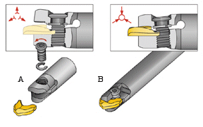
Figure 14: Insert replacement and clamping in endmills for high-speed machining.
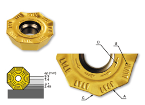
Figure 10: Octagonal insert design for semi-finishing and finishing applications.
The machining of dies, molds and housings depends on the design, the shape, the dimensions and tolerances, the various parts, the die and mold materials, and the sequence of production. One can distinguish between dies and molds for the plastic industry like extrusion, injection molding, blow molding or hot pressing; dies for forging and casting; dies for the production of parts out of sheet metal by sheering, bending or drawing; and dies and molds for powder metallurgy manufacture.
The die and mold material depends on the product material, product design and the production method. For example, molds for the production of plastic parts are made of steel or stainless steel - or even aluminum. Figure 1 shows a half of a blow mold for a bottle, as well as the corresponding pre-mold part produced by injection molding with the upper threaded mouth of the bottle.1 The half mold shown is made of aluminum, while the other mold parts are made of stainless steel.


The machining of these mold parts requires very high accuracy and excellent surface quality to insure a high-quality bottle for sealing purposes and to avoid burrs. Due to the very complicated shape of the mold, the machining is done by various cutting steps and final polishing, with grinding only of the flat surfaces.
Figure 2 shows a die for injection molding of a telephone part (see Figure 2A) and a die for a jet-engine blade (see Figure 2B), which requires strength and hot hardness due to the high forging temperatures and high forces during production.
The die is using a workpiece that is heated up to nearly 800'C. In this case, the forging die material is of high quality steel with excellent heat resistance and requires heavy-duty machining and profile milling. The normal production sequence of an alloy steel die and mold includes roughing and semi-roughing operations, followed by heat treatment and finally the finishing operation to get the high-quality accuracy and surface roughness required.
Most of the final finishing stage consists of grinding due to the high hardness of the parts. Today, producers of dies and molds try to replace the final costly grinding and polishing operations by using hard machining after the heat treatment at semi-finishing and finishing machining conditions. This saves time and money and is possible today due to the development of new geometries, cutting materials and the high-speed machining option. In addition, the more stable machines and high-speed spindles available today make it possible to reach high accuracy even in this hard machining process.
Basic Types of Tool Concepts
For the machining of dies and molds, a very wide selection of cutting tools is necessary. As an example of a complicated shape requiring a large variety of cutting tools, you might observe the lower part of a mounted mold for injection molding of an electronics panel part shown in Figure 3.
The mold requires facing of large and small areas, machining of deep walls or shoulders either by facing or by side cutting, and machining of long, deep and narrow slots. The machining of cavities requires plunging - or ramp down operations - as well as drilling and milling options. The large number of holes requires drilling of small and larger holes, deep drilling, reaming, tapping and chamfering operations. The three-dimensional complicated shape of the mold for the panel itself requires profiling with large- and small-diameter tools as well as special tools. It is essential to reach a very high surface quality and an upper surface layer with low stresses and no distortion.
A variety of cutting tools for the machining of dies and molds is offered by many manufacturers (see Figure 4).} For facing purposes of large surfaces, face milling cutters at A and B with 45', 60' or 75' were used. For 90' slotting and shouldering purposes, milling cutters with arbor clamping of type C and D shown were used. For narrower slots, endmills E and F; and for deeper slots, the heavy-duty G-type with multiple indexable inserts was used. Endmills with full or partial radii on the frontal face H, I and J - with indexable inserts - were used. For profiling, milling cutters with arbor clamping L and M, as well as endmills K and N, were used. Milling cutters O and P were used for plunging and ramp down applications. The ballnose tool Q with indexable inserts and solid ballnose endmill R are typical options for profiling three-dimensional shapes. Tool S was used for 45' chamfering or slotting, and tool T is an endmill with ground, longitudinal, helical brazed or solid cutting edges for larger depths and good surface quality. Additional tools like drills, reamers or sinkers as, for example, the drill U, were used for drilling into small or larger diameters.
The Basic Insert Geometries for Milling
For multifunction operations in machining small slots and shapes, various companies offer a single endmill body on which various interchangeable heads can be mounted. An example of interchangeable heads with a threaded connecting part is shown in Figure 5. The versatility of the system allows shoulder milling, slot milling, small surface face milling, profiling, drilling, chamfering and ramp down operations. This system is recommended with various shank types for machining of dies and molds in various materials.
The main geometries for face-, shoulder- and slot-milling shown in Figure 6 include flat positive inserts, inserts with ground and molded chipformers, and helical, non-flat inserts with modified rake and clearance faces that provide improved performance. For multifunction operations in machining small slots and shapes, you may choose a single endmill body on which various interchangeable heads can be mounted. The versatility of this type of system allows shoulder milling, slot milling, small surface face milling, profiling, drilling, chamfering and ramp down operations. This system is recommended with various shank types for machining of dies and molds in various materials. Other tool producers offer similar or other systems with different clamping devices but with a smaller range of interchangeable heads.
In only a very few facing applications of dies and molds are flat inserts like SPKN, TPKN, the more positive flat SEKN, the flat, screw-clamped ADCA or similar types used. The corresponding older cutter types with wedge or clamped inserts have been replaced gradually by cutters with screw-clamped inserts with a three-dimensional rake face, more chip space and fine-pitch design. The inserts may have a molded chipformer to ease chip formation and exit, and to improve cost efficiency. The inserts also are available with ground corners for better surface quality and finishing operations.
The more positive rake inserts like SEKN, SEKR or SEKT (with screw-clamping) with large 20' relief angles replace the popular 11' clearance angle types because of the stronger, tougher carbide materials available today.
The Helical Cutting Edge Concept
The helical insert types developed during the last few years have a rake angle γC, which is larger than the inserts' axial rake δA (see Figure 6). Insert bottom and top face surfaces are not parallel, which means that the slope of insert bottom face δA2 is smaller than cutting edge angle δA1 - enabling a stronger cutter body.
The concept of the helical cutting-edge geometry is explained in Figure 7a and the equation is shown in Figure 7b.
The helical cutting edge is the intersecting line or curve between the cylindrical outer surface of the cutter and a plane that contains the cutting edge itself. When rotating inserts with this cutting edge around the center line of the cylinder, the resulting machined surface is flat and perpendicular to the frontal face. The curved cutting edge can be determined by the intersecting of the cylindrical surface and the line or plane positioned in the axial angle δA. The curvature R of the helical cutting edge can be represented by the shown mathematical relationship.
It is known that one of the main geometrical disadvantages of a straight cutting-edge insert positioned with a positive axial angle δA is the lack of workpiece sidewall straightness, flatness and perpendicularity.
In addition to the shape of the machined surface, neither the radial rake nor the tangential clearance angles in this type of cutter-insert combination are constant along the cutting edge. These differences in cutting-edge geometry of standard inserts cause changes in wear, forces and chip flow along the cutting edge. The solution to the problem is the insert geometry with the helical, curved cutting edge as well as curved rake and clearance faces, resulting in constant rake and clearance angles on the tool.
This unique design insures flat sidewalls in shoulder, slot and face milling, and solves the geometrical problem of the non-flat machined surfaces that result with the straight cutting edge.
In addition, when using solid endmills or tools with indexable inserts with straight cutting edges and 0' axial rake, the tool enters and exits the workpiece at the same time along its total cutting edge, resulting in vibration, high forces, problems in chip exit and reduction of tool life. Therefore, most of these types of tools are designed with a positive axial angle (φA>0') as shown in Figure 7a.
When using solid carbide tools and indexable inserts with the helical configuration, each cutting edge penetrates gradually into the workpiece with a step-wise force increase, reaching a maximum value which is obviously lower than that achieved with a straight cutting edge. The superpositioning of several cutting edges is a clear advantage of the helical design in respect to the tangential forces and tool deflection. When the cutting edges overlap each other, the resultant cutting forces are lower, the tools are always under load, stability is improved, vibration reduced and the required forces and machine power during the milling operation are lowered. The use of solid endmills and inserts with the helical configuration enables a larger axial angle and geometry with constant rake and clearance angles. Due to the large radial rake angles on the side and frontal cutting edge, the chips are deformed and the sidewalls remain perpendicular, even when machining with small diameter endmills.
The sloped cutting-edge inserts shown in Figure 8 with thicker frontal ends act to strengthen the cutter body and enable machining with higher loads and feeds. While the frontal edge is at maximum strength, the rear side has a smaller insert wedge angle, but is subjected to lower cutting forces. The inserts also are equipped with wiper flats, which act on the frontal machined surface to improve surface quality.
Square, Multi-Purpose Helical Inserts for 90' Shouldering, Facing and Slotting
The most recent and growing family of inserts are square, helical shapes for improved economy and performance. These new square insert geometries combine the helical cutting edge on all four edges with an additional wiper on one of the extremities to perform for 90' sidewall milling operations. The typical insert designs shown in Figure 9 have helical edges at the central part of each cutting edge, while sloping downward or upwardly in the wiper area. The unique design with the wiper insures high surface quality and stable machining. The upper surface is designed with very positive rake angles to reduce forces and improve chip flow. The inserts are clamped with a relatively large axial angle on endmills, shoulder cutters, slotting cutters and facemills and also can be clamped on milling cutters with 45' for chamfering operations and drill mill cutters.
The unique features of the square insert design offer the possibility of using each of the four corners for machining flat, straight and perpendicular shoulders. The helical-cutting edge inserts can be mounted on facemills, T-slotting and slotting cutters, endmills and heavy-duty cutters. The heavy-duty cutters with multiple inserts have full-effective helical cutting edges, providing the possibility to machine at unlimited depths.
Octagonal Inserts for Multi-Function Semi-Finishing and Finishing
New octagonal inserts shown in Figure 10 offer eight cutting edges for more economical facing, shouldering, slotting, recessing and chamfering applications.
Inserts combining helical cutting edges, the large axial angle and a rib-type rake face design offer a self-balanced, stable tool for cost reduction and high performance in semi-finishing and finishing of dies, molds and housings.
The special protruding wiper flat design on each of the eight cutting edges offers good surface finish. Inserts are normally available in the economic M-pressed-and-sintered versions with ground wipers for even higher surface quality. The arrows on the rake face indicate the indexing direction to insure maximal usage of the cutting edges at small cutting depths, as shown in Figure 10. At larger depths - for example, 3.7 mm and more - the number of effective edges is less than eight.
The rake face of the new insert is equipped with a sequence of depressions to reduce the contact area between the chips and insert rake face to reduce heat penetration into the insert, to reduce friction and to improve tool life (see Figure 11). The positive rake angle - in combination with these depressions - also reduces cutting forces and machining power, improves chip flow and extends tool life.
Inserts for Ballnose-Type Endmills
For machining small dimensions, various HSS, brazed tools and solid carbide endmills are used. Normally up to about 8.0 mm in diameter, all tools are solid, while larger diameter endmills are more and more made with indexable inserts. Small endmills are ground on the periphery, on the rake face and on the frontal edge, either with square 90' shapes with a corner radius or chamfer or with a full radius as on ballnose endmills. Rake angles are very positive to reduce forces and improve chip flow, while the possible clearance angle depends on the strength and diameter of the tool. Indexable inserts or endmills with brazed tips are produced with various geometries according to the material and conditions.
New endmills with larger diameters (≥8 mm) are equipped, for example, with helical cutting edge inserts, as shown in Figure 12. The frontal centerpoint is located in the center of rotation and the cutting edge moves upward, describing a full radius of the ballnose endmill. The rake angle is very positive, in order to guarantee a softer cut and easy chip flow. By using this unique helical shape, total cutting force values are reduced, the forces are lower during penetration into the material and the force gradients at entrance and exit are smaller.
Chipformer geometry is designed for the arc-shaped cutting edge used at varying cutting speeds and small to medium feeds. Smaller-size tools have a single cutting edge, and tools with more than 10 mm diameters have two ground edges for balancing and high surface quality.
The overall insert and tool design of small diameter tools can use positive or negative inserts. Positive inserts are normally weaker and reduce tool strength. The use of a negative insert configuration (see Figure 12) with a helical side cutting edge positioned above center provides the necessary relief angle as shown in Figure 13. This unique insert design is clamped with a torx screw in the dovetail seat with sloped sidewalls (see Figure 13, section A-A) in order to provide safe and secure holding. The cutter body design provides a larger cross section and a stronger cutter body with excellent performance even as an 8 or 10 mm diameter tool - and at higher cutting speeds.
For high-speed machining at higher cutting speeds and feeds, solid endmills are normally recommended. In some cases, screw-clamped or blade-type inserts also can be used. Figure 14 shows the clamping device for indexable inserts in medium-size endmills. The inserts have a sloped-blade configuration with a unique clamping to insure safety at higher cutting speeds. The horseshoe type insert is clamped against three points on the cutter body. The resiliency of the upper jaw and the self-clamping effect improve insert holding.
The upper jaw is lifted by rotating a screw, enabling the insertion and positioning of the sloped-blade insert into the seat. By rotating the screw in the opposite direction, the frontal part of the upper jaw is lowered, making contact and exerting clamping pressure on the insert. The larger size of the rear area of the insert acts to retain the insert in place, even at high cutting speeds.
REFERENCES
1Euromold Spezial 3/97, article on the subject of Rapid Prototyping, "Viele fYhren...," pp. E10-E16.
}Werkstatt und Betrieb 130 [1997] 12, Werkzeugfamilie für den Werkzeug-und Formendau.
3Helical Cutting Edge, EP 392730, Iscar 1990.


Related Content

End Mills, Drills, Inserts and More for Mold Building Needs
This list of cutting tool-related products that MMT editors have recently published provide readers a good look at what is being offered in the industry for their everyday operations.
Read More
4 Cutting Tool Challenges and Solutions
A combination of cutting tool carbide, coating and geometry helps tackle four mold machining challenges and improve cutting performance.
Read More
Modular Tooling Systems Enable Versatility in Hole-Drilling Operations
The versatility of replaceable cutting edges offers users the ability to adapt to varied operations.
Read More
Ten Things You Need to Know about Circle Segment Milling
Considerations for evaluating if circle segment end mills or conical barrel cutters are right for your mold machining applications.
Read MoreRead Next

Looking Sharp
Advancements in cutting tool/toolholder construction yield better stability and higher accuracy to achieve greater feedrates and increased productivity.
Read More
Your Guide to Smarter, Faster Mold Design
Dive into expert-curated content delivering proven solutions for mold optimization, manufacturability and precision performance.
Read More
How to Use Continuing Education to Remain Competitive in Moldmaking
Continued training helps moldmakers make tooling decisions and properly use the latest cutting tool to efficiently machine high-quality molds.
Read More