
In Simulation We Trust
Are you taking full advantage of simulation technology?
Some CAD systems come equipped with directly integrated mold flow simulation capabilities that help save time setting up simulations, checking designs and evaluating design alternatives.
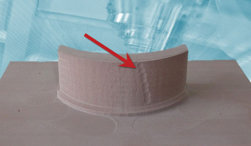
G-code driven VNCK simulation can reveal issues resulting from unwanted repositioning of the rotary machine tool axes near a kinematic singularity of the machine tool. This can be simply fixed by adjusting the tool tilt angle in the CAM system.
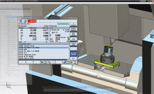
A virtual machine tool inside the CAM system can be used for postprocessed NC code validation, setup, training, and even manual editing of NC code just like at the real, physical machine.


We all know that simulation technology delivers benefits but, as with most technology, we don’t typically take full advantage of it. Simulation has a lot to offer to mold manufacturing. It’s a matter of recognizing the problems that it can help solve.
While we challenge ourselves to find new ways to compete, take on tougher jobs, diversify into new markets and even add new product lines, today’s economic climate dictates that not only must we deliver a job done well, but we must get it done right the first time around. For this reason, the need for simulation technology has become inescapable for mold manufacturers.


Simulation technology has the ability to help optimize parts designs, predict mold performance and validate our decisions. With simulation-driven best practices we can tackle the most complicated jobs—and do them while facing the pressures of overly-aggressive schedules and scarce resources. It can also help achieve business objectives by avoiding costly mistakes that result in inaccurate quotes, incorrectly estimated cycle times, errors in production, wasted material, as well as process inefficiencies.
The following is a brief look at some recent trends in simulation technology as they pertain to key areas of plastic part production and how to take advantage of it from design through manufacturing.
Design Better Parts Faster
Continued advances in simulation technology have made it possible to turn more ideas into volume production much less expensively than before. Part designers can use simulation to understand the relationships between part design, mold design, material and molding conditions which affect appearance, material selection, molding machine requirements, as well as cycle time.
Ease-of-use improvements to Finite Element Analysis (FEA) tools—such as integration directly into the CAD environment and automatic generation of 3D mesh models—enable designers to easily set up and run simulations to predict the strength, vibration, flow and fill performance of designs. While advanced capabilities for simulating specialized molding processes like insert molding, over-molding and multi-shot sequential molding give designers the freedom to explore more complex, innovative designs without the need for physical prototypes.
In automotive for example, fuel prices and the continuing climate debate have stimulated an increase in lightweight materials usage to reduce the overall weight of vehicles and thus contribute to lower fuel consumption and emissions, while maintaining safety. With advances in the modeling of the anisotropy of reinforced plastics and improvements, crash and fatigue life prediction simulations are promoting the discovery and prove-out of innovative alternatives to standard designs. As a result it seems that just about every vehicle component could be up for a makeover—lightweight replacements for brake pedals, door systems, shock absorbers, and even axle systems are on their way to volume production now.
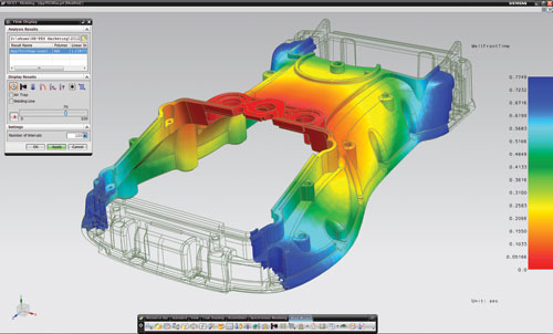
While a part can be manufactured to specification and dimensionally correct, if it has a visual defect, it’s scrapped. For parts that depend on appearance, designers are using filling simulation to predict melt front progression and to guide their decision-making and avoid design elements that, when manufactured, can render parts visually unacceptable. Mold flow issues such as weld lines, air traps, short shots and sink marks can all be properly accounted for during the design phase. In some cases, these mold filling issues can affect physical performance as well, as in the case of weld lines in fiber-reinforced materials.
Make More Complex, Higher Quality and Better Performing Molds
Foreign competition is evaporating the margin on simple tools, driving the need to take on more complex jobs. What's more, the complexity of parts is rapidly surpassing the in-house know-how needed to mold them. Fortunately, simulation-driven design methods can address a range of issues in order to help engineer more complex, higher quality and better performing molds.
Because of simulation, the trial-and-error approach to prove-out tools on the shop floor is rapidly becoming a practice of the past.
Beyond just the simple interference and clearance analyses, tool kinematic motion and assembly / disassembly can now be digitally simulated and validated directly inside the CAD system. Runner systems and gate configurations can be evaluated and molding and pressure drop issues avoided without conducting any actual tool try-outs by using mold filling and cooling simulation to determine optimum gate positions and balance melt flow.
Slow cycle times decrease a company’s cost advantage. Inadequate thermal management within a mold is a common contributor to poor tool performance. Cooling time can occupy the majority of an injection cycle and can also contribute to non-uniform shrinkage—leading to warpage issues. By simulating true 3D material flow through the mold cavity and the heat transfer from the injected plastic to the water lines, it’s possible to optimize a mold’s design to achieve optimum fill and cooling times. Cooling analysis can also be used to determine ejection temperature - the earliest acceptable time to eject - and the optimum locations for and number of ejector pins.
Furthermore, simulation can directly affect profitability by improving the accuracy of quoting and costing activities. By using mold flow simulation technology it is possible to avoid overestimating cycle times, which often results in not winning new business and underestimating that can reduce profits. FEA-based strength analysis and simulation can also be used to assess if a tool is overbuilt and how much excess material (and cost) can be safely eliminated.
Create Error-Free Programs Faster and Machine More Efficiently
Machining simulation is prevalently used by NC programmers to get error-free and optimized programs to the shop floor faster. “Proving out” NC programs digitally prior to machining can save significant job costs. Scrapped parts, material wastage, broken tools and machine crashes are examples of the costly issues that can be avoided. Machining simulation capabilities have even matured to where they can be relied upon to run a first-time part unattended. As a result, many companies have made simulation a standard process step, requiring all programs be verified prior to releasing to the shop floor.
As more 5-axis and multi-function machines are commissioned for mold machining, simulation will play a more prominent role in the NC programming process. While these complex machine tools can reduce the number of setups, machine faster and produce a better surface finish, they also are considerably more complicated to program and there is greater potential for crashes and gouges, thus driving the need to verify programs in the context of the machine tool using machine tool simulation.
Machine tool simulation comes in various levels of capability that can serve different purposes:
Toolpath-driven machine tool simulation drives a 3D machine model simulation straight from the internal toolpath records of the CAM system. It is the quickest at producing a result, but may not be the most accurate because it doesn’t use or verify the actual postprocessed output.
G-code driven machine tool simulation provides a complete kinematic 3D machine environment for visualizing complex motion. Collision checking and multi-channel synchronization is simulated with the postprocessed g-code output so home positions, special tool change motion, and other content inserted by the postprocessor are checked, minimizing any surprises at the machine tool.
G-code driven simulation with embedded virtual NC controller kernel (VNCK) uses the actual controller software to process the posted output exactly as it would on the real machine and drives the kinematic 3D machine tool model to display the simulation. Instead of relying on generic software approximation, this integrated approach computes accurate machining times for each operation and for the entire machining sequence by considering a complete model of the machine that accounts for its performance and response. This approach provides the greatest level of accuracy and completeness.
A virtual machine tool is a virtual copy of a physical machine tool with exactly the same controller, features, HMI and operator panel. It can be used for training, setup, postprocessed NC code validation and even manual editing of NC code just like at the real, physical machine. Machine tool builders that offer the virtual machines can use it to reproduce issues found at customer sites.
Lastly, some CAM systems are making it easier to create optimized and error-free programs by integrating the complete array of machine tool simulation capabilities right into the NC programming environment. The simulation information is right at hand where it’s needed to make any adjustments or corrections. This approach also eliminates extra steps required for data translation and transfer, design iterations and engineering changes, as well as additional software administration.
In addition, CAM systems are now using aspects of simulation technology to provide a more comprehensive and interactive programming experience—like creating toolpaths by dragging and tilting the cutting tool (along with the machine) in the scene or displaying the current material condition of the part as it progresses through each step of the process.
Summary
Simulation technology can make a significant impact on all phases of plastic part production, from design through manufacturing. In addition to helping avoid costly errors by checking work before doing it for real, this technology can assist in making better decisions that result in better parts, better performing tools and more efficient manufacturing processes. Simulation technology is available inside some CAD/CAM systems and through stand-alone applications. Either way, significant time and material benefits can be gained by using it.


Related Content

How to Analyze and Optimize Cutting Conditions to Reduce Cycle Time
Plastic injection mold design and manufacturing company puts NC program optimization software module to the test. The results were surprising.
Read More
How to Fix Predicted Warpage Before It Happens with Windage and CAD Model Morphing
Applying windage and model-morphing techniques saved toolmaker/molder Sturgis Molded Products the time, cost, headaches of multiple part/mold design iteration loops, cumbersome cooling fixtures, and long molding cycles.
Read More
How to Use Scientific Maintenance for More Accurate Mold and Part Troubleshooting
Discover how adopting scientific maintenance approaches helps improve mold lifespan, minimize failures, and optimize production outcomes.
Read More
Plastic Injection Molding Starts with the Pellet
This summer, let’s get back to the basics. For this summer school basics series, Pellet to Part explores each stage of the plastic injection molding process. This week: what every moldmaker should know about raw materials, including the fundamentals of viscosity curves, Melt Flow Index, Melt Flow Rate, shear and more.
Read MoreRead Next

Software Streamlines Complex CAD Design
Understanding its success in the market, Caprock kept its focus on the design process and, in 2011, decided to upgrade its CAD tools to Solid Edge® software from Siemens PLM Software (Plano, TX).
Read More
Overcoming Pain Points in Moldmaking with AI
Shops that embrace AI as a tool, not a threat, can enhance efficiency, preserve expertise, and attract tech-savvy talent.
Read More
How to Use Strategic Planning Tools, Data to Manage the Human Side of Business
Q&A with Marion Wells, MMT EAB member and founder of Human Asset Management.
Read More