
Hot Runners Help the Balancing Process
When improving injection mold balancing, hot runners can assist in fine-tuning the balancing process.


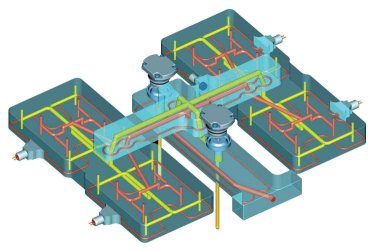
Figure 5: These complex applications illustrate proper balance.
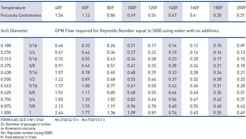

Figure 1: The extra heat in the center of the tool needs to be addressed with proper cooling techniques.
Figure 2: Material viscosity differs throughout the tool due to shear.

Figure 6: Failure to have an increasing velocity causes the melt to go through huge viscosity changes and the cavity filling velocity to decrease.
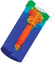
Figure 4: A uniform heat profile maintains a consistent melt temperature over the entire length of the nozzle.
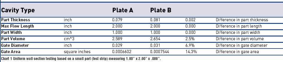
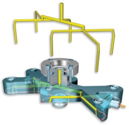
Figure 3: Providing level changes within the manifold can help maintain proper balance.
When more than one gate is required within a system, the question of balance is raised. When running multicavity molds, it's important that all the gates perform identically. This is especially true when molding highly toleranced and thin wall components. If the gates do not all behave in the same manner, the mold is said to be unbalanced. Serious imbalance can result in some cavities being overpacked and sticking in the mold, while other cavities remain underpacked and retain poor dimensional stability.
In recent years, the construction of higher cavity tools and demand for better quality parts has put an increased emphasis on mold fill balancing. Since the majority of these tools incorporate hot runners, at times the hot runner has been falsely accused of being the direct cause for the imbalanced filling of cavities. A poorly constructed hot runner system can cause imbalance. However, a well-built hot runner system, monitored by a top-quality temperature controller, can be a valuable tool to assist the processor in fine-tuning the seven key issues that can lead to mold fill balance:


1. Venting uniformity
2. Uniform wall sections
3. Uniform mold temperatures
4. Effects of shear on melt viscosity
5. Uniform heat profile
6. Naturally balanced manifold design
7. Injection profile and velocities
Venting Uniformity
Nonuniform venting is the number one cause of mold fill imbalance. A common misperception is that venting is acceptable if there is no evidence of burning on a part. However, poor venting can lead to significant backpressure in the cavity; the end result is poor fill balance.
The volume of air in the cavity needs to be displaced by the molten plastic. For example, with a syringe barrel, the size of the syringe orifice will determine how fast the plunger can move forward and how much pressure is required to push the plunger. If a mold exhibits poor venting, it will require more pressure and time to displace the air in the cavity in order for the plastic to fill the volume.
Ironically, the depth and size of vents are often determined by how easily the resin flashes and not by how quickly the cavity fills. When there is insufficient venting, the cavity backpressure makes it more difficult to fill. If all the cavities exhibit the same level of venting, poor or acceptable, fill balance is not impacted. If the venting characteristics across the cavities vary, then the mold fill will be imbalanced.
The best way to check for vent uniformity from cavity to cavity is to perform a pressure leak-down test. By fabricating a fixture specific to your mold cavity or core, you can check venting at the parting line. The fixture needs to be machined flat and cover the cavity parting line. This fixture also requires a pressure gauge and valve shut off. Clamp the fixture to the parting surface, apply air pressure, then close the valve and measure the time required for the air to leak out through the vents. Perform this test for every cavity on the tool. It won't tell you if you have a general venting problem; however, it will tell you if venting is consistent from cavity to cavity.
Uniform Wall Sections
Uniform wall sections are not only critical for dimensional stability of the part, but also affect how fast the cavity fills. An unbalanced fill can be directly attributed to dissimilar wall sections from cavity to cavity. Even very small differences in steel dimensions can yield a large change in part volume. Clearly, a high cavity mold with different part volumes across the cavities will not fill in a balanced fashion.
Chart 1 is based on a small part (test strip) measuring 1.00" x 2.00" x .080". It shows that with a variance of only 0.002 inches in thickness, the part volume changes 2.5 percent.
Applying the same logic to the gate diameter, we can see an almost 7 percent change in gate diameter; however, the flow volume or cross sectional area changes 14 percent. As Chart 1 shows, very subtle changes in wall sections and gate diameters can have a severe effect on cavity balancing.
Uniform Mold Temperatures
Nonuniform mold temperatures adversely affect how resin flows throughout the mold, especially when you introduce a hot runner in the mold base. The extra heat from the hot runner that is built up in the center of the tool needs to be addressed by introducing good water circuit designs and turbulent flow. Proper cooling at the right portion of the mold becomes paramount to maintain consistency-not only from cavity to cavity but also from shot to shot within the same cavity (see Figure 1).
A key factor in proper cooling design is facilitating the correct amount of turbulence in the water flow. A highly turbulent flow dramatically improves the efficiency of cooling circuits-in some cases by as much as ten times. Using Chart 2, one can apply the GPM requirements for any water circuit to achieve turbulent flow. It drastically simplifies applying Reynolds numbers to achieve turbulent flow.
Effects of Shear on Melt Viscosity
Hot runner manifold systems need to be naturally balanced. The melt distance to each gate must exhibit the same flow length and flow diameters. When considering polymer rheology-as the melt flows through the channels and changes direction-the melt can be subjected to shearing thus changing the melt viscosity. On many manifold configurations, this phenomenon can result in the center cavities filling much faster than the outer cavities. This will be more pronounced on manifold systems that are designed on a single rather than a multi-level (see Figures 2 and 3).
Two ways to counteract this phenomenon are:
1. Provide level changes within the manifold;
2. Stack one manifold on top of another creating a level change.
Uniform Heat Profile
Integral heating technology provides heat where it is needed compensating for thermal losses. This provides a uniform heat profile in the manifold and the nozzle.
Conventional nozzles employ heater bands that provide heat to a relatively isolated portion of the nozzle. A conventional nozzle with isolated heat must add additional energy into the polymer in the area of the heater band to achieve a condition where material will flow in the nondirectly heated areas of the nozzle. This added heat energy must be removed during the hold portion of the cycle.
A nozzle with a uniform heat profile maintains a consistent melt temperature over the entire length of the nozzle. Thus the average melt temperature is lower, improving cycle time. Nozzles that also incorporate CICT technology (Conductive Induction Coating) further equalize the temperature gradient across the nozzle (see Figure 4).
When the melt for each cavity has experienced the same, constant heat throughout its journey from the manifold to the gate, the risks of experiencing mold in-fill imbalance are greatly reduced.
Naturally Balanced Manifold Design
In order to achieve natural balance, the material must flow through identical geometry from the machine nozzle to each of the gates. This means not just the same flow distance, but the same bore diameters and the same number of turns along the flow path. This ensures that every gate receives material that has experienced exactly the same shear history in its path to the gate. Natural balance provides the greatest flexibility when processing. With natural balance, the balance is inherent in the design, and is not based on a specific material or processing temperature.
The study of rheology shows that the flow properties of a polymer melt are dependent on both the temperature and the shear that the melt is subjected to. In addition to rheological balance, it is essential that the system is thermally balanced and that the gate sizes are all dimensionally accurate so that all aspects of the system are balanced (see Figure 5).
It is possible to "artificially balance" the flow within a system. This is achieved by selecting bore sizes, which provide a flow restriction and create an artificial pressure drop. In order to accurately predict this, the flow properties of the material must be known, along with the flow rate and the anticipated process temperature. Any variation from the criteria on which the design was based will result in an out of balance condition. Artificial balance is therefore avoided for multicavity molds.
Injection Profile and Velocities
Another big contributor to filling imbalances is not using a proper injection profile for maintaining consistent melt front velocities. When filling a moderately sized part, most injection processors run a straight injection profile (constant velocity) while stepping the pressure as needed. Unfortunately, this does nothing to improve the cavity fill, and in most cases has an opposite effect.
When filling a multicavity mold, the goal is to keep a consistent melt viscosity. The challenge lies in the properties of the resin and two issues that change the melt viscosity during the injection process. One issue is the effect of shear on melt viscosity. As the melt flows through the channels and changes direction, the melt can be subjected to shearing thus decreasing the melt viscosity. The second issue is that all resins exhibit an increase in viscosity in response to an increase in velocity.
Thus, in order to achieve consistent cavity filling velocity and viscosity, the injection velocity needs to continue to increase through the injection cycle. Failure to have an increasing velocity causes the melt to go through huge viscosity changes and the cavity filling velocity to decrease. This has a very direct effect on overall balance of the mold (see Figure 6).
The hot runner is a terrific tool to assist in fine-tuning mold balance, but it too has its limitations. So in order to achieve perfect balance, it's imperative to make sure all these items concerning imbalance fill of cavities are addressed.


Related Content

What Is Design for Manufacturing? Part 1 of 4
A DFM review ensures part design meets injection molding standards, enhancing cycle time, yield and aesthetics. Here are key considerations for the review.
Read More
Three Good Reasons to Switch from Three- to Five-Axis Machining in Moldmaking
Five-axis machining technology is a great tool in the moldmaker toolbox.
Read More
Mold Design Review: The Complete Checklist
Gerardo (Jerry) Miranda III, former global tooling manager for Oakley sunglasses, reshares his complete mold design checklist, an essential part of the product time and cost-to-market process.
Read More
Tooling 4.0: Connecting Industry 4.0 Technology to Your Molds and Molding Process
A packaging supplier applies Industry 4.0 technology to its injection molds so that components talk to each another to understand the dynamics of what is happening inside the mold.
Read MoreRead Next

Hot Runner Justification
How OEMs, molders and moldmakers can better determine when it makes sense to use hot runner technology.
Read More
How to Use Strategic Planning Tools, Data to Manage the Human Side of Business
Q&A with Marion Wells, MMT EAB member and founder of Human Asset Management.
Read More
Overcoming Pain Points in Moldmaking with AI
Shops that embrace AI as a tool, not a threat, can enhance efficiency, preserve expertise, and attract tech-savvy talent.
Read More