
Challenges to Five-Axis Machining for Moldmaking
When considering five-axis machining you must consider your goal for using five-axis machining on molds: to machine the complete part with the shortest cutters possible.


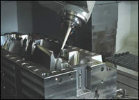
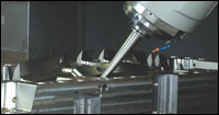
Simultaneous five-axis cutter path with automatic cutter avoidance is used to completely mill this part with the shortest tool length possible.
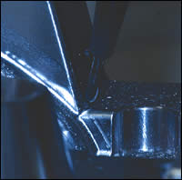
Smaller diameter cutters milling the rest material in the corners can take advantage of automatic five-axis programming to achieve the shortest tool length. Photos courtesy of Sescoi.

Figure 1. Three-axis toolpath. Figures courtesy of Sescoi.

Figure 2. 3+2-axis toolpath.
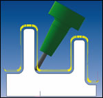
Figure 3. Five-axis toolpath.

More than simple holder collision checking, automatic toolholder collision avoidance is necessary for machining deep cavities of parts with complete confidence. This is especially necessary when utilizing efficiency with machining such as lights-out machining. Combining the automatic toolholder collision avoidance with a large variety of cutter path styles allows for the best efficiency and flexibility in five-axis machining of molds.
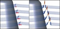
Figure 4. Marked collisions are replaced by radial movements.
Multi-axis milling machines and CAM software for performing five-axis simultaneous machin-ing have existed for many years, and the combination of the two have been used in markets such as aerospace and fluid flow (impellors and propellers) for some time now; however, the uses and market penetration of simultaneous five-axis machining for moldmaking is still in the stage classically referred to as early adopters, with a minority of moldmaking shops using five-axis technology.
Successful five-axis machining requires more than simply purchasing a five-axis machining center and some five-axis CAM software. The machining center must be suitable to machining molds. Similarly, it is not enough to ask if the CAM software has five-axis functions, it must have functions suitable to moldmaking. While a particular CAM package may be very powerful at machining turbines that does not always translate into having functions necessary for machining molds.


The use of short cutters is a key feature of five-axis machining. It significantly reduces the deflection of the tool, results in a better surface quality, prevents reworking, and reduces the number of electrodes and EDM operations. When considering five-axis machining one must consider the goal for using five-axis machining on molds: to machine the complete part with the shortest cutters possible. This includes regular sound business practices of machining the part in a manner that reduces programming, setup and machining times whilst yielding a smooth surface finish.
Three-Axis and 3+2-Axis Machining
The use of three-axis toolpaths [2, 3, 5] is sufficient as long as the part is not too deep with respect to the cutter diameter. If the part is deep and has narrow cavities, using pure three-axis toolpaths is not sufficient for the complete finishing process of the part. This is especially true if milling hard material with long cutters results. In this case bad surface finish and long machining times may ensue. Figure 1 shows the situation for a three-axis toolpath. Here, the minimum tool length must be very long in order to reach all regions of the part vertically.
To utilize a shorter tool the spindle is tilted with an inclined view such that a specific region of the part can be machined with the shorter tool. The process of setting a constant angle to the spindle is generally known as 3+2-axis machining. Complex parts may require dozens of inclined views to fully cover the whole part. The resulting toolpaths must overlap—leading to increased machining time.
Additionally it can be difficult to perfectly blend all of the inclined views, resulting in increased hand polishing. At the same time the number of lead-in and out movements increases dramatically, which often results in surface quality problems and more tool movements.
Finally, programming in this way can be quite interactive and time consuming for the user and often the sum of all views does not cover the whole geometry. Figure 2 shows four views for the part yet there is still a region not covered in the center of the part. This region would still need an additional inclined view.
In order to overcome the drawbacks of 3+2-axis machining, one may choose to implement simultaneous five-axis machining, using functions designed specifically for the moldmaking industry. Simultaneous five-axis machining incorporates the three linear axes and two rotational axes at the same time. It solves all of the problems of three-axis and 3+2-axis machining. The cutter can be very short, no overlapping views need to be generated, the probability of missing an area is much smaller and the machining can be performed continuously without additional lead-ins and lead-outs (see Figure 3).
Five-Axis Milling Machine Considerations
Five-axis milling machines come in different configurations.
- The part can rotate in two degrees of freedom by utilizing a system of rotating tables. In this case the spindle may move axially, but not angularly.
- The milling tool can rotate by having the spindle mounted in a system which provides two degrees of freedom. In this case the part does not move angularly.
- It can be a combination—where one rotation axis is a rotating table and the second rotation axis is provided at the spindle.
Normally when purchasing a three-axis milling machine, one considers several different features such as: horsepower, spindle speed, axial feedrates, work envelope and weight limitations. In addition to these, when evaluating five-axis machines one must also consider the following: repeatability, angular velocity, angular limitations and milling machine controller options for five-axis machining.
Repeatability
Repeatability is the ability for the five-axis milling machine to return to the same point and vector consistently. Repeatability of a five-axis machine requires accuracy of not just the axial positions, but also the angular values.
Angular Velocity
Angular velocity can be considered in degrees of rotation per second, or you may also simply consider it in revolutions per minute (rpm). This is a function of how fast the tool can rotate in relation to the part, the faster the value, the faster the machine can cut. Many older five-axis machines have slow angular movements, which is counterproductive to high-performance machining.
Angular velocity also is important specifically to machining molds. Many five-axis milling machines have a c-axis, which by default rotates around the z-axis. To mill a deep part with a short tool, it is often necessary to incline the tool via the a/b axis and rotate the c-axis to cut around the part. RPM performance of the c-axis is critical to success in this instance.
Angular Limitations
Angular limitations are physical limits to the amount of rotation allowed by the milling machine; these are based on the particular machines design. If it is necessary to incline the tool 50 degrees to utilize the shortest tool or cut an undercut, and you are limited to 30 degrees of rotation, you may not be able to finish everything in that setup.
Angular limitations are very important when considering the c-axis. Many five-axis milling machines have an unlimited amount of c-axis angular movement. However, there are many that are limited in their rotational travel.
For example, a particular mill may only be able to perform +360 and -360 degrees of rotation. Imagine using an inclined angle for the tool and machining down a steep wall, going around and around the part. The majority of the movement in this instance is being handled by the c-axis in a continuous motion. If one has a limited c-axis, it will require the machine to “unwind” at regular intervals to machine the complete part.
Work Environment
Regarding work environment, while you may be familiar with this in a three-axis sense, you also must consider it in a five-axis sense. Does the actual work envelop get smaller as the part or spindle rotates? Using one of your common milling tools installed in the spindle, measure the work envelop with the tool vertical, as well as with the tool inclined to the machine's maximum value.
Different five-axis machines use different five-axis controllers. Some controllers work best when the part is mounted with the origin of the part at the exact intersection of the rotational axes. Some controllers favor using an inverse feedrate option.
Many five-axis controllers contain logic to know exactly where the tool center point is in relation to the part, no matter how many rotations have occurred, while it is in motion. This functionality is often referred to as rotational tool center point (RTCP). Many users find that using advanced RTCP functions makes the implementation of five-axis easier.
Five-Axis CAM Software Considerations
With five-axis machining, the problems of 3+2-axis machining are not removed; they have been shifted from the programmer to the CAM system. In order to use short tools on the entire part, collision control becomes the most important consideration. It is simply not enough for the CAM system to find collisions between the part and the tool and holder, but it must automatically avoid the collisions, so that the CAM programmer does not have to manually modify the inclination angle of perhaps tens of thousands of data points, or more.
Unlike five-axis functions for specific parts like turbine blades, airfoils and impellors, the five-axis functions for a moldmaker are different. Moldmakers do not necessarily need to cut “normal” to all of the faces in the CAD file, they need simply to rotate the inclination angle just enough to automatically avoid collisions between the tool, holder and the part.
When evaluating CAM software for machining molds, especially deep molds there are many things to consider:
- Flexibility of five-axis functions
- Reliability of five-axis cutter paths
- Ease of use
- Five-axis milling machine limitations
- No five-axis solution possible
Flexibility
Flexibility in five-axis milling strategies is an important feature to consider. If one is using a three-axis CAM package with several milling strategies, why would one settle for having just a few five-axis strategies?
One novel approach which provides flexibility is a module inside automatic toolpath generation software for surface or solid models in mold, die and tooling businesses. Simply put, the module automatically converts a three-axis cutter path to five-axis, rotating the tool inclination angle enough to avoid collisions. This allows for great flexibility, because all three-axis finish cutter path strategies are then available for five-axis use.
Reliability
Reliability of the five-axis cutter paths is critically important. With the addition of the two rotation motions in five-axis the chance for collisions greatly increases, thus the collision checking and avoidance must be reliable, or else suffer damage to expensive equipment.
If one is not completely confident in their CAM system’s three-axis software, then they will not be confident in that company’s five-axis offerings. If a company is not willing to run their three-axis cutter paths unattended, they will not be able to trust their five-axis cutter paths.
Ease of Use
Ease of use and five-axis programming were once thought to be mutually exclusive. Traditionally, five-axis programming was considered difficult, time-consuming and extremely interactive. That paradigm must change in order to remain competitive. Utilizing a program such as automatic toolpath generation software for surface or solid models in mold, die and tooling businesses, creating five-axis cutter paths is as simple as creating three-axis cutter paths. It allows shop floor programming in five-axis for complex deep parts using the CAM software to avoid collisions.
Five-Axis Machine Limitations
Five-axis machine limitations can affect how one chooses to perform five-axis machining on a mold. CAM software must be able to simulate the particular five-axis machine and adjust the cutter paths to avoid running into a rotational limit. If a particular five-axis machine has a limit on the c-axis, the CAM software must be able to place the necessary unwind movements into the cutter path, all the while maintaining a collision-free cutter path.
Additionally, many five-axis mill configurations have varying limits on their a/b axis. Many trunnion style machines can rotate in the a axis negative 90 degrees, but allow only 15 degrees positive rotation. For this reason, it makes sense that the CAM software automatically takes this limit into consideration to avoid running into limits in the positive direction.
No Five-Axis Solution Is Possible
Sometimes, no five-axis solution is possible. This occurs when the tool is so short, or perhaps the holder is so large that no matter what inclination angle is tried, a collision will always result. Does the CAM system stop at this point, does it fail to produce a cutter path at all or does it inform you of the problem areas?
Naturally, forcing a lot of trial and error on the user, recalculating entire cutter paths is counterproductive. It is best if the problem areas are highlighted, with the possibility of using a longer tool, smaller toolholder or simply editing out those points.
Figure 4 shows an area with points where no inclination angle produced a safe cutter path. Subsequently the points were automatically removed so that the majority of the part could still be cut with the short tool.
Conclusion
Simultaneous five-axis cutter paths can be used to machine an entire part with a short tool instead of requiring very long tools as would be required in a strictly three-axis environment. Five-axis machining can reduce the amount of electrodes and EDM operations necessary. Simultaneous five-axis machining can reduce problems with 3+2 axis machining, such as creating many inclined views, and blending all of the inclined views.


Related Content

Plastic Injection Molding Starts with the Pellet
This summer, let’s get back to the basics. For this summer school basics series, Pellet to Part explores each stage of the plastic injection molding process. This week: what every moldmaker should know about raw materials, including the fundamentals of viscosity curves, Melt Flow Index, Melt Flow Rate, shear and more.
Read More
How to Analyze and Optimize Cutting Conditions to Reduce Cycle Time
Plastic injection mold design and manufacturing company puts NC program optimization software module to the test. The results were surprising.
Read More
Three Good Reasons to Switch from Three- to Five-Axis Machining in Moldmaking
Five-axis machining technology is a great tool in the moldmaker toolbox.
Read More
Tips for Tackling Mold Design, Machining, Cutting Tool and Wear Challenges
Tips for tasks ranging from reducing risk in part design and taking advantage of five-axis machining to refining cutting tool performance and reducing wear with guiding and centering systems.
Read MoreRead Next

How to Achieve Economical Five-Axis Milling
Although moldmaking has not had great incentives to invest in five-axis technology like the aerospace industry, there are still many reasons for moldmakers to adopt five-axis machining, and there are a few interesting software functions that help to make five-axis programming economical.
Read More
High-Speed Machines Deliver Speed, Accuracy, Repeatability and Finish
The addition of high-speed machines that blend a reasonable cost with high performance helps one moldmaker realize a huge competitive advantage.
Read More
Five-Axis Machining Is a Key Requirement for High-Precision Molds
Design and fabrication capabilities of advanced tool-cutting processes give toolmakers an edge in developing new business.
Read More