Bringing Greater Process Control to Moldmaking
Advances in machine accuracy, on-machine probing technology and non-contact toolsetting provide powerful tools for automating and speeding mold machining.
Drives to faster, leaner, more flexible manufacturing are shifting industry focus away from traditional post-process quality control. The most expensive, non-value-added process in most shops is part inspection. Inspecting good parts—parts that meet all print specifications—is a waste of time, money and manpower. Rather than back-end detection, attention is shifting to front-end prevention. The aim is to make 100 percent good parts, right the first time, to ever-tighter tolerances in the lowest possible total processing time.
Under that mantra, a variety of practices and technologies are being applied to machine tools to achieve greater process control. Automated process checks can keep process and parts in control, while minimizing downtime for operator intervention.
These process control improvements can be particularly vital for moldmaking. The one-off nature of most mold/die work and the high accumulated value that can go into a complex mold demand right-the-first time processing. At the same time, shorter leadtimes and global competition force the need for faster mold processing. By minimizing need for operator intervention, these process controls give moldmakers an eye on the job during long machining runs and lightly staffed second and third shifts.
Front-end prevention takes three forms:
- Identifying and maintaining machine capability
- In-process probing
- Automated tool monitoring
Machine Capability
In order to move from defect prevention, you must be able to document your process capability and the accuracy of your machine tools. To do this, inspect them to a nationally recognized and accepted standard, such as ISO 230 or ASME B5.54. Both call for a ballbar and laser interferometer to be used with a recommended procedure for checking machine tool accuracy.
The purpose of these standards is not to specify an accuracy the machine must meet, but to find out what accuracy level it can meet—its process capability. The part print dictates the accuracy your machine must have to make good parts—where to set the accuracy bar. Testing tells you how high your machine can jump. As long as your machine can top the bar, you have process capability.
Test and calibration technology are now available—and affordable—to enable shops to ensure the accuracy and health of their machine tools. Plants and large shops increasingly maintain their own laser interferometers and electronic levels, while rental equipment and diagnostics services are commercially available to small shops from various sources and competitively priced.
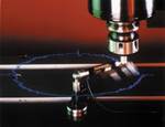
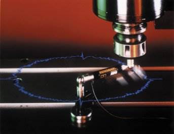
Telescoping ballbars are readily affordable by virtually any shop and provide a fast, 15-minute check-up for prevention and diagnosis in maintaining machine accuracy. The ballbar test allows precise assessment of machine geometry, circularity and stick/slip error, servo gain mismatch, vibration, backlash, repeatability and scale mismatch. Some ballbar software provides diagnosis of specific errors in accordance with ISO 230-4 and ASME B5.54 and B5.57 standards, then provides a plain-English list of error sources rank-ordered according to their overall effect on machine accuracy. This allows maintenance people to target those factors that need the most attention.
Periodic ballbar testing enables trend tracking of machine performance. Preventive maintenance can be scheduled before a machine drifts out of process capability. The industry trend is to calibrate the machine on need, not time. There is no reason for maintenance to pull a perfectly good machine out of production for calibration. Let the ballbar and the accuracy of your parts determine when something has gone awry. In the meantime, run production!
On-Machine Probing
Today’s standard machine tools can deliver accuracy and repeatability approaching levels formerly available only on CMMs. This enables the machine tool itself to be used for probing checks of workpieces during critical stages of the machining process. Once a machine tool’s performance as a measuring instrument has been established, the probe becomes the operator’s CNC gauge. Probing routines can be programmed as part of the machining process and automatically run at various points to check feature dimensions and locations and apply necessary compensations. This saves operators from using dial indicators and shim stock, or eliminates errors in manually entering fixture, part and tool offsets into the control. Probing on the machine makes it part of the process—a powerful process improvement tool for making parts right the first time in the shortest throughput time.
Setup
Used to locate the part automatically and establish a work coordinate system, probing cuts setup time, increases spindle availability, lowers fixture costs and eliminates non-productive machining passes. On complex parts, 45 minutes of fixture alignment can be replaced by 45 seconds of probing—performed automatically by the CNC. When starting with a casting or forging, probing can determine workpiece shape to avoid wasted time in air-cutting and help determine best tool approach angle.
In-Process Control
This uses probing to monitor size and position of machine features during the cutting process, as well as verify precise dimensional relationships between various features at each step to avoid problems. A probe can be programmed to check actual machined results at various stages against the program and automatically apply cutter compensation—particularly after rough machining or semi-finish machining.
Reference Probing
Reference probing is comparing part features to a dimensional master or reference surface of known location or dimension, which enables the CNC to determine positioning discrepancies and generate an offset to make up the difference. By probing the artifact before a critical machining pass, the CNC can check its own positioning against the master’s known dimensions and program an offset. If the dimensional master is mounted on the machine and exposed to the same environmental conditions, reference probing can be used to monitor and compensate for thermal growth. What results is a closed-loop process requiring no operator intervention.
Every machine has its own set of numerous small errors in its motions and structure. As a result, there always is a slight discrepancy between a CNC’s programmed position and the true position of the tool tip—even after laser compensation has brought the two into closer agreement. Programmable artifact probing provides a way to further compensate for remaining machine errors. It gives process control feedback to enable positioning accuracy that can approach the machine’s repeatability specification. Such closed-loop process control can allow a machining center to achieve accuracies comparable to boring mills and other high precision machines.
Fail Safe Operation
Many probing operations are accomplished through the use of memory-resident macro programs. Work coordinate updates, tool geometry changes, part measurement, etc., are automatically determined by the CNC after the successful completion of a probing cycle. This eliminates costly errors resulting from mis-keyed information or incorrect calculations.
Final Inspection
Used to inspect parts after machining, probing can reduce the length and complexity of offline inspection, and in some cases eliminates it altogether. Inspecting on the machine is particularly beneficial with large, expensive workpieces—such as molds or dies—which can be especially difficult and time-consuming to move.
Here, too, reference probing can be accomplished using two methods, machine correlation—comparing on-machine measurements to prior CMM data, or artifact comparison—comparing on-machine data to a traceable artifact of known size. When making this comparison, the CNC can determine if the specific machining tolerances were actually achieved. Based on these results, an intelligent decision can be made on corrective actions, while the workpiece is still on the machine tool.
Non-Contact Laser Toolsetting
Laser toolsetters provide a fast, auto-mated means to verify tool dimensions, especially critical in checking for wear during the long machining runs in moldmaking.
A cost-effective solution to high-speed, high-precision tool setting and broken tool detection, laser toolsetters rapidly measure tool length and diameter on-the-fly, while the tool is indexing through the laser beam and rotating at normal speeds. Laser checking at working spindle speeds identifies errors caused by clamping inconsistencies and radial run-out of the spindle, tool and toolholders—not feasible with static toolsetting systems. Some NC toolsetters can perform broken tool detection at maximum traverse to further minimize out-of-cut time.
As the tool moves through the laser beam, system electronics detect when the beam is broke and issues an output signal to the controller. NC systems can accurately measure tools as small as 0.2 mm diameter anywhere in the beam. The system triggers when the laser beam is broken beyond a 50-percent threshold by the tool being checked. The non-contact toolsetting system uses a visible-red diode, laser proven reliable in machining conditions.
Advanced electronics and simplified design makes non-contact toolsetting an affordable alternative to contact systems. No moving parts make NC systems virtually maintenance free. The design avoids the brackets and actuators with contact-based systems.
Housed in a rugged stainless steel unit, some NC laser toolsetters feature a protection system, which uses a continuous stream of compressed air to keep out contaminants and provide uninterrupted protection from chips, graphite and coolant ingress, even during measuring routines.
Some NC systems enable installation on nearly every size and configuration of machine tool without impinging on the work envelope.
Powerful Process Improvement Tools
These proven, affordable control tech-nologies can allow greater automation of mold machining with greater process control. They can make it possible for moldmakers to produce molds faster, with greater geometric and dimensional accuracy, and less operator intervention, rework or manual finishing.
Related Content
It Starts With the Part: A Plastic Part Checklist Ensures Good Mold Design
All successful mold build projects start with examining the part to be molded to ensure it is moldable and will meet the customers' production objectives.
Read MoreTooling 4.0: Connecting Industry 4.0 Technology to Your Molds and Molding Process
A packaging supplier applies Industry 4.0 technology to its injection molds so that components talk to each another to understand the dynamics of what is happening inside the mold.
Read MoreTips for Tackling Mold Design, Machining, Cutting Tool and Wear Challenges
Tips for tasks ranging from reducing risk in part design and taking advantage of five-axis machining to refining cutting tool performance and reducing wear with guiding and centering systems.
Read MoreWhat Is Scientific Maintenance? Part 1
How to create a scientific maintenance plan based on a toolroom’s current data collection and usage.
Read MoreRead Next
The Center of Automation
Macro pallet-mounted gage balls reduce overall costs in electrode machining/manufacturing and reduce leadtime by 25 percent.
Read MoreThe In's and Out's of Ballbar Calibration
This machine tool diagnostic device allows the detection of errors noticeable only while machine tools are in motion.
Read MoreHow to Use Continuing Education to Remain Competitive in Moldmaking
Continued training helps moldmakers make tooling decisions and properly use the latest cutting tool to efficiently machine high-quality molds.
Read More
