
The Effect of Pressure and Temperature on Part Quality and Dimensions
Injection molding is a complex system of machinery, fluid dynamics, and thermal conductivity. And that’s just the tip of the iceberg. Let’s simplify it. Let’s break the mold down into two simple parts, the heat exchanger and the pressure vessel, and review how they can impact overall part quality and dimensions.


To start, let’s review how plastic makes a journey from pellet form to a liquid or a sliquid (a semi-scientific term that identifies a substance that is neither a true liquid or solid) in the injection unit.
For those unfamiliar with British Thermal Units (BTU), it represents the amount of thermal energy necessary to raise the temperature of one pound of pure liquid water by one-degree Fahrenheit. To melt plastic, there’s a certain amount of BTU content that must be added to a semi-crystalline, like polypropylene, to break that structure down and turn it into an actual liquid. Breaking these crystal structures takes an enormous amount of energy in comparison to amorphous resin. Amorphous materials, like polycarbonate, technically never melt, they only get softer.
Most of us don’t think about processing plastic in BTU content, but rather we think about melt and heat deflection temperature (HDT). That is the temperature at which a polymer or plastic sample deforms under a specified load. From a thermal dynamic perspective, we only need to remove about 40% of the BTUs required to melt or soften the plastic before it is ejected from the mold. The remaining 60% of the BTU content is lost to the atmosphere during post mold cooling. We will not go into the equations necessary to understand the energy it takes to melt the plastics, but below in Figure 1 we can see the difference in cooling based solely on material selection.
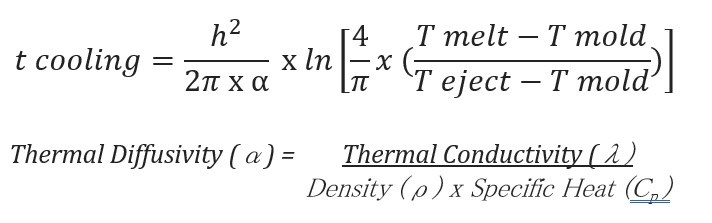
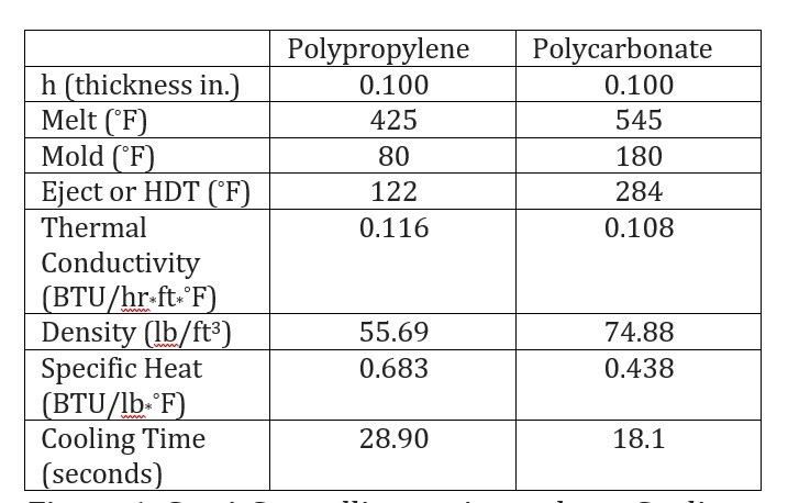
When reviewing the temperature of the melted plastic in comparison to the temperature at ejection, there is an average of 62% decrease in temperature (shown in Table 1). During process development, it’s much easier to measure the melt and part ejection temperatures.
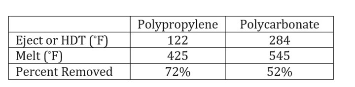
Table 1: Semi-crystalline vs. amorphous temperature comparison.
How efficiently the 40% is removed is ultimately based on where the water lines are placed, type of metal used in the mold, and the ability for the plastic part to give up its heat (referred to as thermal conductivity). In this scenario, the plastic is an insulator and is the overriding factor in achieving efficiency. The better job we do as engineers at designing the mold (shown below in Image 1), the faster the cycle time will be. In an ideal world, there would be no temperature variation across the part when it’s ejected from the mold.

Image 1: Starting point for cooling channel design.
However, we know in most circumstances this is not feasible. Instead, a reasonable temperature differential of less than 20°F will yield acceptable results. In most circumstances, sinks, voids, and variation in gloss level will be detectable immediately after ejection. When the part temperature after eject is over this 20°F, there’s a likely chance you’ll end up with warp. With certain materials like Polyoxymethylene, we have to be aware that this post-mold shrinkage can sometimes take days or weeks to stabilize. Below (in Image 2), a part with thick sections shows a considerable temperature differential at ejection.

Image 2: Toy plane fuselage.
Pressure Vessel
The mold is a pressure vessel, and its influence on part quality is enormous. We are going to break this system into sections: the melt delivery system and the cavity. Since the first interaction the plastic has with the mold is the melt delivery system, we’re going to start here.
When we look at the melt delivery system, it is important not to undersize the system to ensure there is minimal pressure loss from the nozzle machine up to the gate. In most cases, semi-crystalline needs the smallest size, followed by amorphous, and bringing up the rear would be glass or fiber filled materials of any type. At a high-level we can start to look at the MFI (shown in Table 2) of these resins. We can see in general a viscosity of each particular resin and the MFI ranges. The lower the MFI, the larger the system needs to be sized for effective filling and packing of the cavity.
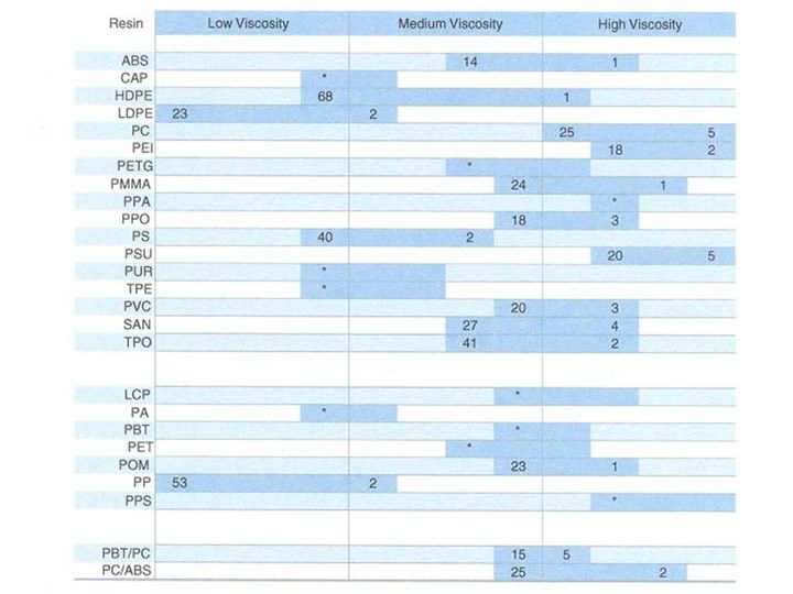
Table 2: Viscosity and MFI ranges.
When designing the melt delivery system, it’s advised to work from the part towards the molding machine. Gates are the starting point—if undersized, it increases the filling pressure and reduces the ability to pack out the cavity. It can also increase the shear rate, which can lead to degradation of the polymer chain.
Parts with high viscosity and low MFI will likely need more than one gate to ensure the pressure loss across the cavity is not too large. Once the correct gate type, size, and quantity is determined, the journey back to the machine nozzle continues. Runner, drop, or manifold lengths should be kept as short as possible between cavities, making sure there is still adequate spacing for water lines, as previously mentioned. The higher the cavitation gets, the more difficult it becomes to manage the pressure loss.
Lastly, keeping a cold runner sprue or hot runner inlet length to under 2.000 in. is advisable. Below (in Image 3) is an example of a multi-cavity family, which exhibits vastly different flow lengths resulting in vast changes in pressure and cooling rate in the mold cavity.
We know the highest pressure in the injection molding process is at the machine nozzle, while the lowest is at the end of fill within the mold cavity. In order to minimize defects like sink, void, warp, short shots, and dimensional instability, we as engineers have to manage the pressure loss across this entire system.
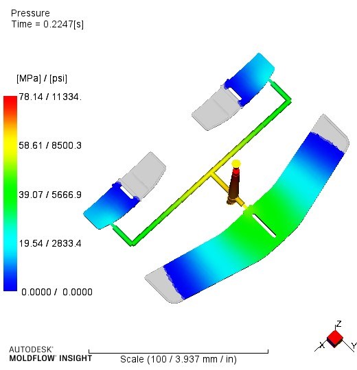
Image 3: Multi-cavity family.
As we can see through these few examples, it’s critical to manage pressure loss and temperature from the molding machine nozzle tip to the end of the cavity. Otherwise, it could result in dimensional variation and instability.


Related Content

How to Use Scientific Maintenance for More Accurate Mold and Part Troubleshooting
Discover how adopting scientific maintenance approaches helps improve mold lifespan, minimize failures, and optimize production outcomes.
Read More
Tips for Tackling Mold Design, Machining, Cutting Tool and Wear Challenges
Tips for tasks ranging from reducing risk in part design and taking advantage of five-axis machining to refining cutting tool performance and reducing wear with guiding and centering systems.
Read More
Mold Design Review: The Complete Checklist
Gerardo (Jerry) Miranda III, former global tooling manager for Oakley sunglasses, reshares his complete mold design checklist, an essential part of the product time and cost-to-market process.
Read More
Three Good Reasons to Switch from Three- to Five-Axis Machining in Moldmaking
Five-axis machining technology is a great tool in the moldmaker toolbox.
Read MoreRead Next

How to Use Continuing Education to Remain Competitive in Moldmaking
Continued training helps moldmakers make tooling decisions and properly use the latest cutting tool to efficiently machine high-quality molds.
Read More
Your Guide to Smarter, Faster Mold Design
Dive into expert-curated content delivering proven solutions for mold optimization, manufacturability and precision performance.
Read More
Overcoming Pain Points in Moldmaking with AI
Shops that embrace AI as a tool, not a threat, can enhance efficiency, preserve expertise, and attract tech-savvy talent.
Read More