
Rigorous Mold Tryout: Do Your Homework
If moldmakers strive to understand how an end user will use the mold, they will help their customers become more profitable and more confident in the shop’s abilities leading to a strong partnership.


The goal of a rigorous mold tryout is that a mold can be transferred into any appropriate molding machine, on cycle by the least qualified technician and make the first shot into production a verified good part.
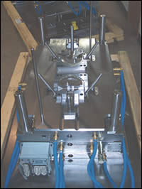
One of Extreme Tool’s new molds ready for a rigorous mold tryout.
How do I know if the customer is giving the mold a chance to perform? How do I know if the customer has the mold in the correct machine? How do I know if this machine is even capable? Why, when we adjust the tool steel to meet the dimensions, are they not correct the next time the customer tries the tool out? We have modified this mold six times and it still is not correct!
These are a small sample of questions that cause process problems and cost money. With increasing pressure from a global economy and local competition we need to be more thorough in bringing the mold to production at a faster rate. If we understand more facets of how the end user (the processor) will use the mold, we as tool builders can help them reach that success to be more profitable, build more confidence in our abilities and develop a partnership.


Doing Your Homework First
We start by doing our homework first, prior to cutting steel and during the quoting stage. Most part drawings come in a solid model format, which is a benefit for deciding shot size and clamp force. For example, we will use a part called an AB switch housing. By doing a query for the cubic inch volume of the drawing (in this case revealed .382 cubic in.), I take the specific gravity (1.14) of the material (ABS) that this part will be molded in. This gives us a good indication of the shot size of .435 cubic inches for a one-cavity mold, if the mold is not under packed or over packed.
The customer suggested that this mold would be used in an 85-ton molding machine with a 4.4-oz shot size (screw diameter of 1.417 in. and a stroke of 5.12 in.). This machine would have the capability of moving 8.07 cubic inches of material. Typically, it is best to use 20 to 80 percent of the 8.07 cubic inches for a robust process.
Cavitation Based on Machine Selected
Cavitation suggested by the customer was two, which will create an unfavorable condition. This would only be a shot size of .87 cubic inches, and if this were a cold runner, we would add for the runner as well. If it is for a hot runner we do not need to include anything more. This is a problem because injection speed may never be reached.
For example, I set two cones on the road a 100 feet apart and ask you to drive your vehicle up to the first cone. I then instruct you accelerate up to 80 miles an hour and stop at the second cone. Now several problems become evident. First, you probably will not reach 80 miles an hour or you may slide past the second cone due to momentum. The molding machine may respond in a similar manner as your auto, thus reducing the capability of the processor.
Another item to consider is residence time. As with two cavities there will be many shots stored in the barrel, which could create the opportunity for degradation (too long at temperature).
In the case of the machine the customer wants to use, a shot window of 1.6 cubic in. (20%) to 6.46 cubic in. (80%) should be considered. A better cavitation would be four (or possibly more if warranted), which would create a shot size of 1.74 cubic inches. This would help the processor to be able to use a larger range of injections speeds, therefore allowing a larger process window. We could validate this later when the mold is completed and in the molding machine during the rigorous mold tryout.
Now, if you use more than 80 percent of a barrel’s capability another problem needs to be considered. If the residence time is too short it may affect the homogeneous mix of the material.
Mold Base Size
So, now that we have selected the cavitation based on the machine selected, we now need to consider the mold base size. The customer suggested that this machine has a tie bar spacing of 16" x 16", which is our next piece of the puzzle. In order to discourage platen deflection (and all molding machines have some level of platen deflection), we need to cover at minimum two-thirds of that area between the tie bars. Anything larger will only be a bonus, to the point of not being able to install in the machine between the tie bars depending on installation from top or side.
Tonnage
Next, we need to decide how much tonnage this mold will require by again using the solid model. If we were to slice the model at the parting line and then query for the square inches in that plane, then multiply that times the tons per square inch from the material data sheet, the ABS that we will use indicates that two to five tons are needed. I will use three tons per square inch. The equation to use is:
1.1309 sq. in. of part x 4 cavities =
4.5236 sq. in. x 3 tons/sq. in. =
13.57 tons necessary to support this mold.
Again, the molding machine that has been selected has an 80-ton capability that we must try to match. If a four-cavity mold is built and used in this machine, the opportunity for over clamping and encouraging platen deflection will be prevalent—as this machine may not be able to adjust to a setting that low. A more accurate way of determining the tonnage requirement are cavity pressure transducers, one near the gate and one at end of fill. Through data acquisition you would add the post gate pressure to the end of cavity pressure then divide by two; this will give the average pressure across the cavity. Next divide that number by 2,000 to convert to tons. Using a flow analysis may help in determining cavity pressures.
Reconsidering Cavitation
Now, we need to reconsider the cavitation as four cavities are not the best. Six or eight cavities should be considered. If the customer does not want that many cavities or the budgetary numbers do not support that amount of productivity, then a smaller molding machine should be considered.
Future Considerations
After a final decision has been made for the correct shot size, correct tonnage and mold base size, we can then look at runner design if warranted. We will look at runner design and mold design in successive articles.
Another issue of concern is whether or not the molding machine has enough performance to push and pack the plastic in the mold. Part complexity, long flow fronts and some materials require higher plastic pressures to overcome them. We may need to understand intensification ratio to understand the plastic pressure in a hydraulic machine. If it is an electric machine, we just need to know the available injection pressure. This topic also will be discussed in a future article.


Related Content

Mold Building Stats Improve Performance
Mold manufacturing is a numbers game rooted in measurement and data tracking to continuously improve.
Read More
Dynamic Tool Corporation – Creating the Team to Move Moldmaking Into the Future
For 40+ years, Dynamic Tool Corp. has offered precision tooling, emphasizing education, mentoring and innovation. The company is committed to excellence, integrity, safety and customer service, as well as inspiring growth and quality in manufacturing.
Read More
How to Improve Your Current Efficiency Rate
An alternative approach to taking on more EDM-intensive work when technology and personnel investment is not an option.
Read More
MMT Chats: Championing Moldmaking Recruitment
Production manager is doing his part to help transform skilled trades recruitment through strategic advocacy and digital engagement.
Read MoreRead Next

Overcoming Pain Points in Moldmaking with AI
Shops that embrace AI as a tool, not a threat, can enhance efficiency, preserve expertise, and attract tech-savvy talent.
Read More
Your Guide to Smarter, Faster Mold Design
Dive into expert-curated content delivering proven solutions for mold optimization, manufacturability and precision performance.
Read More