
Optimizing Mold Design with Scanning Technology
How to use scanning as a primary source of data collection.
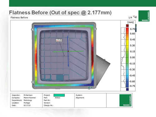
The M+H part was measured during first article inspection and some critical features were found to be out of spec. This would typically cause a potential leak path, so the decision was made to correct the issue prior to DV (design validation) testing. In this case, they had prior knowledge that the tool was cut directly to CAD, but with standard shrink rates applied to this cavity.
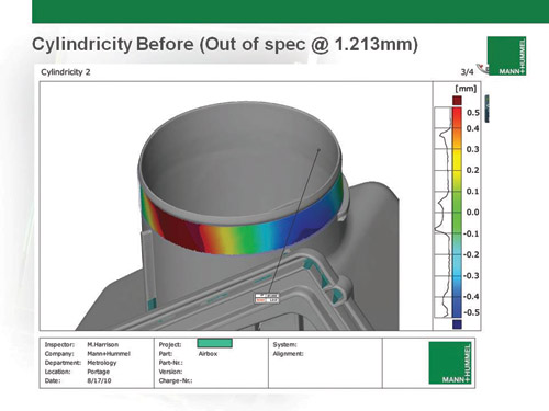
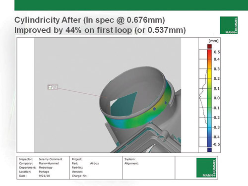
The red areas are clearly high, and the blue ones are low, relative to the nominal CAD model. A histogram beside the legend shows the deviation distribution between the part and CAD for each dimension. This is a rather simplistic example, but the data for these two critical dimensions was gathered in minutes, and the compensated surfaces as well as the decision to move forward was generated in hours, not days, of analysis.
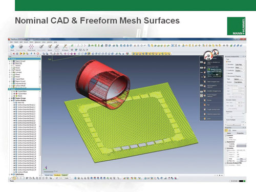
To correct dimensional issues and supply the tool shop with ready-to-use surfaces, the nominal CAD and part mesh are imported into the surfacing software. The areas of interest are then isolated into surfaces, which will be corrected, and each surface boundary is extended by fitting a freeform surface to each isolated mesh.
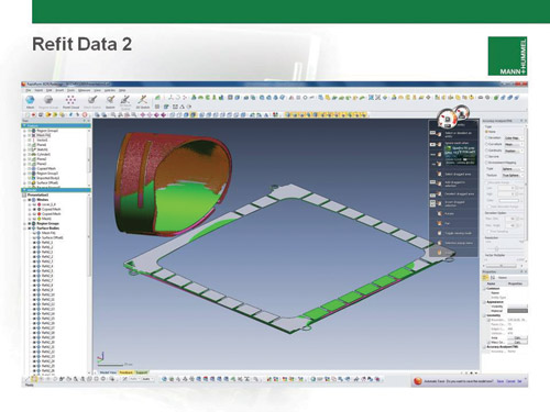
The nominal CAD surface in grey, the part mesh triangulation in brown, and the refit CAD surface for the tool shop in green. Only the latter surface needs to be sent to the tool shop to generate the required cutter paths. For this part, one option was steel removal only, thus theoretically improving the part quality by only half. This would still get the part within acceptable limits and minimize tool tuning time.
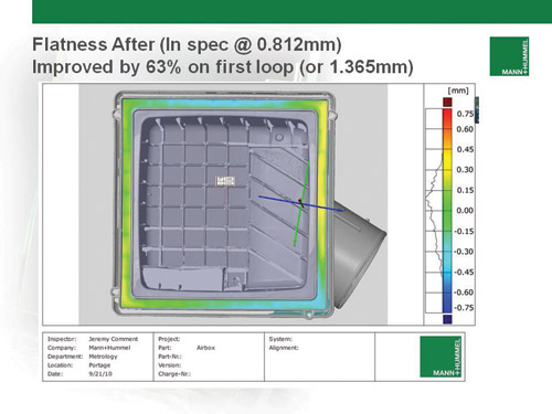
The real-world result for steel removal from the tool using the surfaces generated above on this project. Based on these figures, the parts have improved by about half, as expected for this case. The injection tool was not welded up as it was not necessary to get the part to meet functional and print tolerance.


Scanning at Mann+Hummel (M+H) has rapidly evolved with accuracy and measurement speed more than doubling with direct computer control (DCC) machines during the last three years. This technology is a positive influence in their manufacturing and metrology processes, by improving and expediting the communication of part quality issues and how to correct these issues throughout the supply chain—tooling suppliers, customers and the manufacturer.
M+H implemented scanning and freeform surface analysis to reduce tool tuning iterations for typical under-hood automotive plastic injection molded components, such as windshield washer bottles, coolant reservoirs, intake manifolds and air filter boxes. Their process uses a structured light scanner and surfacing software. 3-D scanning software was added as a resource for multi-piece part inspection.1 The primary improvement is eliminating common communication errors by making tool tuning corrections directly readable by CAD software in their tool shops, rather than providing data solely in a tabular format of XYZ coordinates and deviations, as was standard with their tactile DCC CMM probing process.
Three-Layer Compensation Process
M&H’s preferred process is to use tool-compensated CAD surfaces in a generic format (i.e. Parasolid, .IGES, or .STEP) that are ready to use, based on the inverse deviations of the scanned part data. M&H employs a three-layer compensation process beginning by scanning a part and/or computing the average of multiple scanned parts and importing the reference CAD model. Most scanners have the option to export .STL files into meshing software to process polygonal meshes. These files look like CAD models, but are organized and connected point clouds accurately representing the measured part. Polygonal files can be compared to CAD models or other polygonal meshes to generate deviation color maps highlighting the differences between the nominal or the part-to-part variation—making it easy to spot significant dimensional issues with manufactured parts.
These files can be analyzed further to create full dimensional reports. Highly accurate part meshes are comprised of too many triangles to be used as substitutes for CAD models in up/downstream CAD/CAM software. The meshes need to be processed further by surfacing software2 that idealize the part mesh surface, and in a simplistic sense, reduce triangle count and surface connectivity to a manageable format. This is a necessary step if the data is to be used for tool correction. These software programs have tools for reverse engineering a scanned part for times when a nominal CAD model is not available.
To create scanned data that is tool-compensated and ready to use requires specialized tools, and prior knowledge of the mold used to make the measured part. Most importantly, this is the nominal surface and mold surface relationship. When these two surfaces are the same, the three-layer standard refit solution is acceptable for use. It may be necessary at times to apply additional tuning corrections on a tight tolerance tool or conditions where the CAD and tool surface relationship are not the same. In these cases, the three-layer process does not work. M&H created a new process to solve the problem.
Four-Layer Compensation Process
Applying the three-layer method to a mold that has been compensated produces a negative effect to the quality of the part. Therefore, M+H devised a process to compensate mold surface conditions using a more useful, but more complex, four-layer method. The nominal CAD and actual part are still compared via a color plot as in the three-layer method, but additionally, the actual part and mold surface must be compared. The points employed to create the color map must use the actual part data points as the source to pierce the mold data. The latter can be a CAD model or a scanned surface. In doing so, this should result in nearly the same number of points between the two deviation plots. These two plots are exported into a spreadsheet, and then sorted to find the matched pairs of XYZ points using the actual part data points as a reference.
Because there are not many options available to work with point clouds, the imported point cloud must be triangulated by the software into a mesh, and then surfaced to eliminate any irregularities or errors. The resulting idealized surface eliminates noise in the data, but must be converted back into a mesh, which restores the original CAD surface boundaries. In this case, they have already compensated for the mold and part deviation manually using a spreadsheet, and must use a compensation factor of positive 1. This will bring a copy of the nominal surface data directly to the compensated mesh. Pre-compensating the data points now opens up the possibility to use all standard surfacing tools available in these software packages to generate resulting CAD surface data.
The area of tool-tuning reduction is one in which the payback of equipment and software is exceptionally rapid. M+H is looking toward a process to compensate entire cavities, especially for multi-cavity tools where potentially no tuning loops would be necessary. This could apply when there is another cavity available or a when a prototype mold can be used to calculate the optimized tool compensation prior to cutting new cavities or production molds.
Regardless, by implementing these processes with the current set of available OEM software tools, M+H has realized a 200-percent return on investment during the first year of implementation. This program has continually and significant improved part quality while reducing programming timing, in addition to saving M+H costs on tool tuning.
Summary
Further improvements have been realized using inspection software. Scanning has replaced the role of traditional CMM part-to-print dimensional reports, making report generation quicker, easier and more reliable. This advantage assists with tuning loop reductions by making it easier to identify known potential dimensional issues on large projects. They can apply more of the right XYZ corrections into each tool tuning loop, because it is no longer necessary to create a CMM program. They also avoid the cost and complexity of expensive datum fixturing commonly used with tactile probing. These types of under-hood components can be scanned for verification during development and throughout the lifecycle of the program.
By using scanning as a primary source of data collection, M&H performs the traditional role of the tactile DCC CMM to reduce programming timing for manufacturing multi-piece part layouts. They are able to directly communicate the exact cutter path moves required by moldmaking shops in a format that reads directly into their CAD/CAM software. This improves part quality and eliminates one source of error that delayed program launches, where before they had miscommunication, data misalignment or insufficient surface data. Correcting these errors reduces the overall cost and number of tool tuning loops.
References
1 M+H’s process uses a structured light scanner (ATOS) from Capture3D and surfacing software (XOR3) from Rapidform. Polyworks software was added as a resource for multi-piece part inspection.
2 Surfacing software from Rapidform, Polyworks and Geomagic.
Contributor: Jeremy Comment has been with Mann+Hummel USA, Inc. since May 2003, where he has worked as the Senior CMM Programmer since 2006. This article is an excerpt from his technical paper presented at the 2011 Coordinate Metrology Systems Conference hosted by the Coordinate Metrology Society (CMSC.org).


Related Content

How to Quickly Check Cooling Channels
Smart hole inspection validates possible leakages and strangulations in the cooling channels by doing tightness and flow rate tests.
Read More
How Adler's Global Network and In-House Labs Address Complex Mold Challenges
Adler combines 0.0001" tolerances, reverse engineering capabilities, global facility coordination and comprehensive in-house validation labs for seamless mold solutions.
Read More
Automating Mold Inspection: Integrating Speed, Precision and Usability Across Complex Workflows
Whether you're verifying an electrode, checking a complex cavity or feeding quality data into a closed-loop workflow, today’s CMM technologies are turning inspection into a competitive advantage, not a bottleneck.
Read More
MMT's Most Popular Maintenance Reads of 2024
Peruse this past year’s top maintenance content, including topics like inspection/measurement, maintenance and repair and surface treatment.
Read MoreRead Next

How to Save Time and Money with Faster Measurements
Today’s mold manufacturer is often looking for time and cost savings on many levels. There are solutions—whether it is to reduce development times, accelerate the configuration of entire initial sample test reports or shorten reaction times for damage analyses.
Read More
Overcoming Pain Points in Moldmaking with AI
Shops that embrace AI as a tool, not a threat, can enhance efficiency, preserve expertise, and attract tech-savvy talent.
Read More
Your Guide to Smarter, Faster Mold Design
Dive into expert-curated content delivering proven solutions for mold optimization, manufacturability and precision performance.
Read More