


Hot runner tips can have a great influence on part cosmetics. Left to right: sprue style, low-vestige and valve gate. Photo Credit: Incoe Corp.
With advances in technology, hot runners have many more uses today than they did years ago. They are used to eliminate the cold sprue and runner, which can save you money on scrap when regrind is not an option. Hot runners enable direct gating onto the part with a low-vestige tip or valve gate and eliminate the need for three-plate runner systems. They also allow you to gate on the outside edge of the part when it is centered on the mold.
On larger parts where knit lines or flow lines are a concern, you can use sequential valve gates to control the flow and move the knit lines. You can use multiple hot drops to reduce fill pressures. They can be used to eliminate long cold runners to reduce pressure loss and improve the process window.


In short, hot runners have many applications and can be very beneficial to the injection molding process, providing savings in cycle time and eliminating cold runners and sprue. Of course, hot runners can add a significant cost to the tool up front and, therefore, need to be justified economically. However, the payback can be very significant on tools that run higher volumes and/or higher cost resins.
Hot runners do add some complexity to the mold and require added maintenance, but improved designs have drastically reduced issues with hot runners over the years. The terrifying sight of a hot runner pocket and wire channels packed full of plastic can bring instant heartburn. This sight was more common years ago, but in my arena, managing thousands of preventive maintenance (PM) operations and repairs a year, it is not so common anymore.
Hot runners do add some complexity to the mold and require added maintenance, but improved designs have drastically reduced issues with hot runners over the years.
A “Simple” View of Hot Runners
I want to simplify the understanding of the hot runner and its function. First, think of it as an extension of the molding machine itself. Its purpose is to keep the plastic molten at a proper temperature on its path to the cavity. So basically, it’s just a piece of heated steel with a round channel in it for the melt to flow through. Ideally, this channel would be running at the exact temperature on the controller, free of obstacles such as dead spots or components that could create hangups and cause scrap issues with color changes or contamination.
The flow channel needs properly placed heaters and thermocouples to ensure that the correct temperature is maintained. The thermocouple itself is the most critical component. It is what reads the hot runner temperature and tells the controller how much current to send to the heater to maintain the set temperature. In most cases, when there is an issue with temperature, the thermocouple is the root cause, not the heater.
A heater is basically like a light bulb — it’s either working or burnt out — but there are times when it appears to be functioning when in actuality it’s not able to come up to temperature. I will get into how to verify the function of the heater in the press by measuring resistance/ohms.
Suppose a thermocouple is loose or not held tight against the steel whose temperature it is supposed to read. In that case, the thermocouple will be reading the ambient air temperature instead, causing the controller to send excessive current to the heater and result in extreme overheating. I’ve seen this situation cause material in hot runners to spew smoke while the controller was showing that zone to be under the set temperature. I have also seen this happen when the thermocouple and heaters were not wired to the correct zones on the connection plugs.
Years ago, heaters with integrated thermocouples were more common, but they are not reliable for providing an accurate temperature of hot runner components. Because of this, you need to understand how critical the thermocouple and its placement are. Fortunately, most hot runner manufacturers today are very good at thermocouple and heater placement to maintain accurate temperatures without cold or hot spots.
I have also tried to stay away from the old analog-style hot runner controllers. The newer electronic controllers are much more accurate and provide a smoother flow of amps. I have seen a few cases where just changing controllers to the newer technology eliminated issues with parts.
One case involved brown streaks on a polycarbonate (PC) part. We spent much time working on the hot runner and process with no improvements, but the controller ended up being the issue and when we changed it, our issue disappeared. Another case concerned a part that had a specification on reflectivity. We were receiving erratic results, but with a controller change, our issue was also eliminated.
This article aims not to endorse or discourage hot runner use but to offer a user-centric perspective on their role in daily injection molding.
Tips on Tips
Many times over the years, hot runners have been a source of concern over dead spots where the material can hang up and degrade. With today’s hot runner designs, this is not an issue in most cases.
The one area of the hot runner that causes the most headaches with part cosmetics is the hot-drop tip. The other areas to consider are the orifices on the hot runner and the nozzle tip. Hot runner designs have seen many technical advances in tip designs and styles, which have helped with cycle times and gate vestige, but these components are obstacles in the flow path and can cause hangups.
There are three general styles of hot-drop tip designs, with many variations of each: The low-vestige, straight-through sprue style and the valve gate.
- The low-vestige tip is used to direct gate onto the part with minimal vestige and is also used on cold runners to reduce stringers. But I have found, in most cases, that this tip style is not a necessity. It can increase fill pressures (pressure loss) and contribute to color issues when running multiple colors. This tip style will also plug easier, as the orifice has less volume/area. This can be a big headache when running regrind with this style of tip.
- The straight-through sprue style tip is usually the least problematic for color changes and contamination, without as many areas for the material to hang up. But even with some of the new designs today and with an insulating gap, even a sprue-style tip can create problems. Most systems provide components to fill these gaps, commonly known as color seals.
- Valve gates are used to direct gate onto the part with minimal vestige and are also used to control the flow when using multiple valve gates. Because they can be shut off independently, you can control flow fronts and knit-line locations.
Tip designs over the years have evolved drastically, with a focus on improved color changes and temperature control at the tip orifice to combat opposing tendencies toward either freeze-off or drooling. Color changes alone can be very costly in terms of scrap and machine time. But for each plastic material, different tip variations are needed to optimize color changes and temperature control at the hot-drop tip and orifice. I am writing from experience with a broad range of materials, so some of this info may not line up with your particular issues if you are confined to running specific materials.
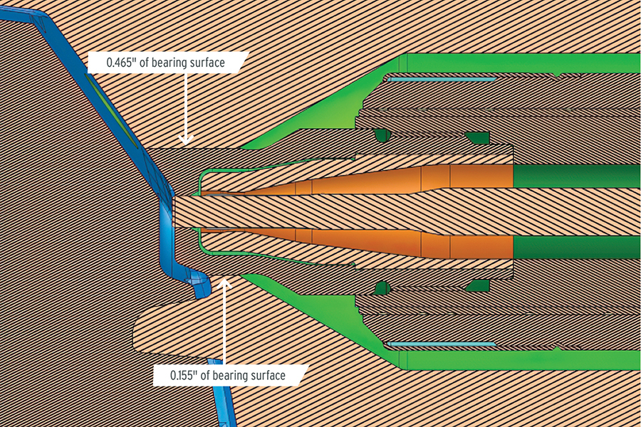
A common assumption about hot runners is that reducing the bearing contact surface between the nozzle tip and the cavity steel is desired to minimize heat transfer. In my experience, the opposite is most often true. Photo Credit: Deppe Mold & Tooling
Dispelling a Myth
One area I would like to clear up is bearing/contact surface and cooling at the hot-drop tip. I have run across the assumption many times that a reduced bearing surface between the hot-drop tip and the cavity steel is desirable to minimize heat transfer. In my experience, the opposite is true in most — though not all — cases when dealing with drooling, stringing and sprue sticking. Although there is no universal prescription, I wanted to stress this point, because getting to the root cause of an issue can become a challenge when opinions and assumptions get in the way of understanding what is really going on.
I can count on both hands the times over the past 28 years when I had to reduce bearing/contact surface to solve a hot runner problem. In fact, lack of sufficient cooling and bearing/contact surface has been more often the case.
The few times I have had to reduce bearing surface was when dealing with freeze-off at the tip orifice, requiring excessive pressure to push plastic through — if it was possible at all. These cases involved using cheaper grades of PC and nylon. Reducing the contact between the tip and cavity steel keeps the nozzle tip hotter because you are not allowing the cooler cavity steel to pull as much heat from the tip area. As I mentioned last month, most new tip styles have insulator gaps to reduce heat transfer. But these also can cause issues, and in some specific cases, I do not recommend using them.
In most cases, I have observed over the years a lack of focus on cooling in the tool itself around the hot-drop tips and gate area. It would make logical sense to me that you would want to concentrate cooling in these areas when you have a component that can be hotter than 500ºF. When you have a sprue-style hot tip and are seeing problems of sprue sticking, the root cause is typically lack of cooling — either from inadequate water in the tool or lack of contact between the tip and cavity steel. The same is true with drooling issues.
From what I have learned, these problems can be material-specific. The two materials that come to mind for sprue sticking are glass-filled nylons and PC/ABS. I have had to modify many tools over the years by adding waterlines to the tip area and increasing the contact surface to resolve these issues.
Often Overlooked: Gate Orifices
Nozzle orifice size has a big impact on processing window and part aesthetics. But with low-vestige tips like this one, be sure to take into account the orifice area lost to the spreader. Photo Credit: Deppe Mold & Tooling
One area often overlooked when addressing hot runner problems is the orifice size. This alone can impact all of the issues mentioned above, as well as the process window and scrap rates. Many are hesitant to play with the tip orifice, although it alone can resolve many issues. But I do not recommend just diving in without some experience and understanding of the impact of orifice size changes — and the possible need to go back to where you started.
The orifice is often overlooked with regard to fill pressure when gating into a cold runner. I have seen numerous cases where people focus on the runner and gates when the tip alone was the root cause as the main point of restriction in the flow path. Pressure drop studies are very beneficial to understand this but are not always used. A pressure drop study helps you understand where your pressure loss is occurring. Shoot just through the injection nozzle, then through just the hot runner orifice, and then the part. (With a cold runner, you shoot through the nozzle, then the runner, then just through the gate and then the part.)
Orifices can have more of an impact on the process than just pressure. A case in point is one where I was dealing with a high gate vestige from a valve gate. The part had 0.110-inch nominal wall stock and was center gated with a valve gate orifice of 0.250 inch. I’m not the process guy, but I was asked to get involved to see if there was anything we could do to the tool. The process window was small: Any slight change in fill speed or time could create a high gate. But a change in back pressure would not create one.
Nozzle orifice size can also cause or relieve processing problems with valve gates. Changing the orifice size is relatively easy by replacing the seat insert and valve pin. Photo Credit: Deppe Mold & Tooling
So, my first decision was to reduce the valve gate orifice. With today’s options, it was as easy as ordering a new seat insert and a new valve pin. I went down to a 0.160-inch-diameter orifice. The results were very interesting. With the gate area reduced by half, a slight change in back pressure would create a high gate and any change in fill speed would not create one. With this puzzling result and a process window that was still not robust, we hadn’t improved the situation.
We then changed the valve gate orifice to a 0.210-inch diameter, which left a gate area midway between the original size and the smaller one. The results again were very interesting. We ended up with a robust process window where we could not create a high gate with either a change in speed or back pressure. I have a couple of theories as to why the orifice size had such a big impact.
I also ran across a scrap issue caused by splay, where changing the orifice size ended up being the solution. This was a part with four low-vestige tips, which have a spreader tip in the center of the gate orifice. In this case, the overlooked factor was the amount of gate area taken up by the spreader tip, which restricts flow.
In this case, the orifice was 0.050 inch and the spreader tip in the center of the gate was 0.025 inch. The area of the spreader tip reduces the gate area by 25%. The fill speeds with this gate needed to be on the high end to make a good part, but we struggled with a lot of splay. We opened the orifice size to 0.060 inch, which gave a 55% increase in the effective gate area not occupied by the spreader tip. This enabled us to adjust the fill speed and eliminate our shear and splay issues.
Igniting Insights
Having entered the plastics industry in 1988, I’ve witnessed a remarkable transformation in hot runners. From crafting them out of raw steel to managing molds globally, my hands-on experience includes building custom tips and maintaining various hot runner brands. This article aims not to endorse or discourage hot runner use but to offer a user-centric perspective on their role in daily injection molding. I hope it did its job.
Next month, I will wrap this series up with thoughts on maintenance and troubleshooting of hot runners.
Updated and republished from Plastics Technology.


Related Content

Advantages and Disadvantages of Copper and Graphite Electrodes
Both copper and graphite provide approximately the same end result, so it is important for a shop to consider the advantages and disadvantages of each material in order to discover what would work best in their shop floor environment.
Read More
Hands-on Workshop Teaches Mold Maintenance Process
Intensive workshop teaches the process of mold maintenance to help put an end to the firefighting culture of many toolrooms.
Read More
Treatment and Disposal of Used Metalworking Fluids
With greater emphasis on fluid longevity and fluid recycling, it is important to remember that water-based metalworking fluids are “consumable” and have a finite life.
Read More
Machining Center Spindles: What You Need to Know
Why and how to research spindle technology before purchasing a machining center.
Read MoreRead Next

New Blog Series: The Designer's Edge
Here's to a new year and a new bi-weekly blog series by guest blogger Randy Kerkstra that will offer ways to design and use the mold for effective troubleshooting and for yielding the largest processing window possible. We appreciate Randy's willingness to share his passion for solving problems and lessons learned throughout his 27 years in mold building and molding. We hope this series begins an ongoing dialogue on how mold shops can have a bigger impact on the molding process.
Read More
How to Transition From a Cold to Hot Runner Mold
Reducing cycle time and costs while also freeing up your machines for other projects are advantages gained by using hot runners that no one can ignore. But where does one begin transitioning from cold to hot runners?
Read More
How to Make an Informed Hot Runner Decision
A proper hot runner assessment requires evaluating and calculating key runner system variables.
Read More