
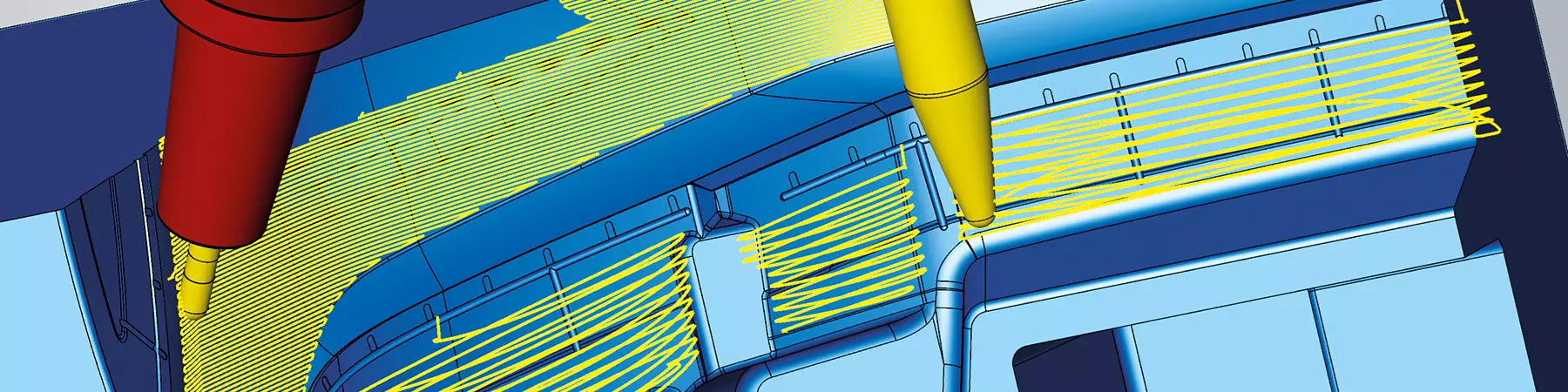


A smooth overlap function in CAD/CAM software helps in many situations including two adjoining tool paths with different cutters and different orientations. Source (All Images) | Open Mind Technologies
Investment in five-axis machining centers and adoption of multi-axis technology has been the winning formula for many shops. Shops that make this investment seldom regret it. Yet, the overall adoption rate of five-axis machinery with American mold builders and job shops remains low compared to other developed countries.
Let’s review some of the key benefits of multi-axis technology and explore how some multi-axis programming techniques can expand potential manufacturing solutions for mold builders.


For example, implementing multi-axis technology enables creative fixturing and manufacturing approaches, increases opportunities to bid on more work, and achieves higher shop rates and profit margins. Five-axis processing also aligns with newer design concepts, including the manufacturing of monolithic parts rather than a set of individual subcomponents and making parts with more complex geometry. Last but not least, five-axis machining can be used for finish machining operations after processes such as additive manufacturing (AM).
Multi-Axis Technology Efficiency Gains
Let’s take a closer look at three primary benefits of transitioning to multi-axis technology:
- Shorter tooling and cutter stick-outs that pivot the cutter and holder away from a part surface. The new tooling setup has benefits that include lower cost and added rigidity that allows higher feed rates than cutters with longer stick-out. It also has less deflection than a longer cutter, resulting in improved surface finishes and longer tool life.
- One workpiece setup — as opposed to multiple operations — that reaches features on multiple sides of a part or compound angles. In addition to the time and cost savings when using one setup, quality improvements are realized without having to reset a part in a new fixture and assure alignments.
- Reduced setups that decrease the number of machine tools, reducing the amount of required floor space. Many shops have limited floor space, so minimizing the number of machines while maximizing multiple processes in one five-axis machining center can increase productivity, avoid a building expansion and eliminate the need to redesign the shop floor.
Implementing multi-axis technology enables creative fixturing and manufacturing approaches, increases opportunities to bid on more work, and achieves higher shop rates and profit margins.
ROI Opportunities
The basic talking points are merely the tip of the iceberg. These introductory reasons alone justify the acquisition of five-axis capabilities. However, once you have a multi-axis machine, the benefits increase exponentially.
These three approaches can increase your return on investment:
- Five-axis simultaneous tool paths are not required in every case on a five-axis machine tool. The user can benefit from software capable of providing high-performance indexing and simultaneous solutions. There are benefits from using 3+2 machining techniques (both rotary axes fixed) or 4+1 machining techniques (typically, the pivot axis is fixed and the rotary axis has free motion). These processes have technical benefits when applicable, primarily to stiffen the machine dynamics, enable higher feed rates and achieve consistent surface finish. Also, some larger machine tools are not very dynamic, so 3+2 motion is preferable.
- Automation within CAM software can identify multi-axis holes and pockets and create frames or cutting orientations that ease programming tasks and enable machine control functions.
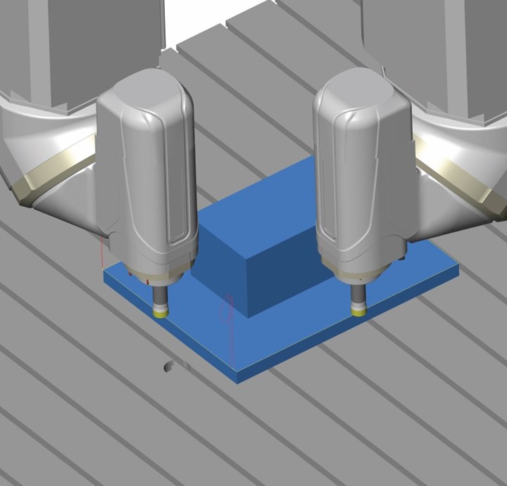
- For production-oriented parts, a pyramid fixture is used like a traditional tombstone device on a horizontal machine. It can enable multiple parts to be manufactured in one setup, with multi-axis potential and without shuttling pallets in and out of the machine. A pyramid fixture can also move the cutter orientation away from the “pole,” which is a mathematical singularity, and further improve the machining efficiency.
Versatile Machining Options
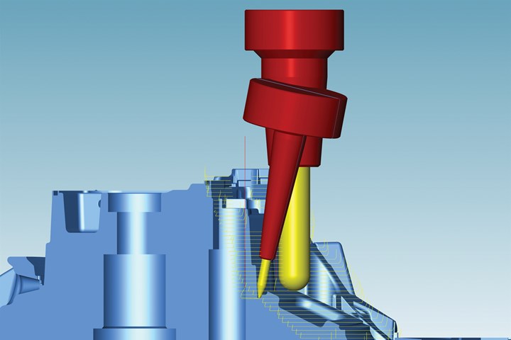
There are also creative solutions to consider for your five-axis machine. For example, when a large milling machine has an asymmetric head, a three-axis process is typically used to perform roughing operations. However, at increasing depths, the head may interfere with the core or cavity shape. Advanced CAM software can identify this and use the fourth axis on the machine to rotate the spindle away from collisions and continue the roughing operation with added safety.
An NC optimizer function in CAM software can enhance an NC operation to avoid machine collisions. Here, it is modifying a three-axis roughing routine to rotate the C-axis to avoid collision with the asymmetric head.
Other machines may have a limited linear axis stroke or interference zones, such as trunnion motors or a coolant block. Optimizations that identify these components and use rotary motion can avoid collisions and streamline the five-axis machining process.
Then there is five-axis helical drilling. This is an enhanced technique over traditional three-axis helical drilling. The five-axis technique is more of a roughing process to open a bore or make a start-hole before a roughing operation. The three-axis technique is effective, but the cutter removes metal on the bottom and back sides of the cutter and recuts chips. The five-axis technique uses the available axes on the machine to lean forward and only cut on the front edge of the cutter. The chips fly out behind the cutter, enabling higher feed rates and longer cutter life.
Smooth overlap is another valuable technique. It is used to blend adjacent tool paths or even the steep and shallow areas of a tool path commonly used on mold components during slope-based processes. The result is an imperceptible blend zone that mitigates the need for manual or other subsequent finishing processes.
A common application is blending a Z-level finish on a part surface followed by rest machining, typically with a smaller end mill to form a fillet radius. From a theoretical CAD/CAM perspective, there should be a perfect blend between adjacent tool paths. In a real-life situation, many factors may cause a minor mismatch, including tool length settings, machine kinematic precision, machine temperature, ambient temperature throughout the day and deflections between the two different cutters.
The smooth overlap technique slightly increases the toolpath width without double-cutting previous tool paths. Smooth overlap removes the mismatch without measuring and negates the need for fitment of the final tool path. A mold builder can also apply this process to three-axis machines. However, it is more common on five-axis machines where a smaller tool is used for rest machining and set at a different orientation for collision avoidance than the primary cutter used to machine the surface.
For many mold machining applications, whether for automotive or packaging, the appearance of the end product may be as important or even more important than geometric accuracy. Achieving a consistent machined finish that does not require manual polishing provides a substantial benefit and saves time on overall workflow processes.
Finally, another technique is finish-machining a component that was prepared with an AM process using five-axis machining, even if the part would ordinarily be produced with a three-axis process. Additive processes can impart high temperature and stress.
When finish-machining a part that may have thermal deformation, a three-axis machining process might not be used. The residual stock may be imbalanced, or the part is outside of its intended design envelope. You can correct finish-machining by probing and using a best-fit adjustment to ensure you meet part quality requirements.
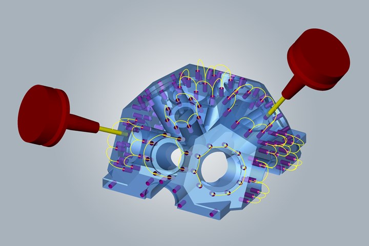
Multi-axis drilling with automatic orientation determination and smooth connection between holes.
Implementation Advice
In the current technological environment, the move to five-axis machining should be incremental, making it achievable for all-sized manufacturers while yielding substantive benefits. Adoption rates continue to expand, and the risk associated with this investment is much smaller than if it was made 10 or 20 years ago.


Related Content

How to Correctly Size a Hydraulic Cylinder
This week Randy shares steps for correctly sizing a hydraulic cylinder on a mold.
Read More
The Benefits of Hand Scraping
Accuracy and flatness are two benefits of hand scraping that help improve machine loop stiffness, workpiece surface finish and component geometry.
Read More
Surface Finish: Understanding Mold Surface Lingo
The correlation between the units of measure used to define mold surfaces is a commonly raised question. This article will lay these units of measure side by side in a conversion format so that companies can confidently understand with what they are dealing.
Read More
Plastic Prototypes Using Silicone Rubber Molds
How-to, step-by-step instructions that take you from making the master pattern to making the mold and casting the plastic parts.
Read MoreRead Next

Reducing Risk to Implement CAM Software Successfully
Following a training and implementation period, new software technology can provide a strong return to the business and be key to long-term success.
Read More
CAM Automation is a Process, not a Goal
Automated NC programming requires a strategy to yield improved productivity, quality and consistency.
Read More
Broadening CAM Applications for Barrel Cutters
This alternative cutting tool geometry, along with the right CAM software, can help moldmakers reduce finish-machining times.
Read More