
The Common Ground Between Moldmaking and Aerospace
Many of the proven technologies used for mold and die machining can also be used in difficult to machine aerospace materials.


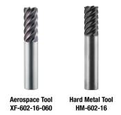
Figure 4. Aerospace geometry versus hard metal geometry pictures.
Figure 1. Radial width of cut guide. Figures courtesy of RobbJack.
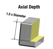
Figure 5. Axial depth guide.
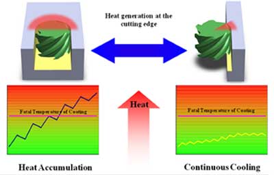
Figure 3. Continuous cooling graph.
Figure 2. Radial width and heat generation chart.
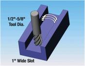
Figure 6. Trochoidal toolpath illustration.
Now that there are more pressures on mold and die manufacturers to find additional work, an area that might be a reasonable leap for mold and die shops is aerospace machining. Many of the established technologies for mold and die machining can be used in the difficult-to-machine aerospace materials. With the influx of titanium, inconel, and high-temperature alloys needing to be machined for commercial and military aircraft, there is a need for more advanced machining techniques. Many of the new aerospace techniques have been utilized in the mold and die industry for years.


Controlling Heat
Some of the problems with machining hardened tools steels are the same for difficult aerospace materials. One major common area of concern is controlling heat and an effective way to control heat is to reduce the radial width of cut. Radial width of cut is the distance between centerlines of successive, parallel cuts. Typically the radial width of cut should equal 2 to 10 percent of the cutter’s diameter (see Figure 1).
Radial step-over determines how much heat is accumulated in the tool and the part by determining the length of time each flute spends in the cut and the amount of time it cools before entering the cut again. Figure 2 illustrates the effects of radial step-over and heat generation.
Controlling the step-over of the tool has been used for years by tool builders for successful mold manufacturing, but recently this technique has gained momentum in aerospace machining. When the step-over is too great, the flute builds up heat because it spends too much time in the cut and there is insufficient time to cool the flute before it reenters the part. By using smaller step-overs, there is a continuous cooling action that controls heat generation.
By regulating the heat generation with a continuous cooling action, higher RPMs can be used without reaching the fatal temperature of the coating. Once the fatal temperature of the coating is reached, there is a rapid deterioration of the cutting edge, which increases force and temperature to the tool and part. When the proper process is implemented there should be no build-up of heat in the part (see Figure 3).
Coating
By selecting the proper coating, higher temperatures can be reached without compromising the cutting tool. For example, the maximum working temperature for Titanium Carbonitride (TiCN) is 750°F (400°C) compared to Aluminum Titanium Nitride (AlTiN) with a maximum working temperature of 1470°F (800°C). Generally, AlTiN is the preferred coating for HSM of hardened die/mold materials as well as difficult aerospace materials because of its high heat resistance. The higher heat resistance of the AlTiN coating enables the use of faster RPMs without damaging the cutting tool.
One major distinction between aerospace alloys and mold and die materials is that flood coolant is used in most aerospace alloys. High-pressure coolant is becoming more popular and has shown to increase tool life in difficult materials like titanium.
Feeds and Speeds
Proper speeds and feeds are essential in controlling heat buildup. Large chip loads remove heat with the chip so it does not build up in the tool or part. If the chip load is too light there is a rubbing or grinding type action that leads to heat buildup. Therefore, it is very important for tool life to use the largest chip load possible without damaging the tool or part.
For example, if the chip load per tooth should be 0.005" and the chip load used is .0025", a part that should take 20 minutes to machine now takes 40 minutes. This means the tool spent twice as much time in the cut than required.
Geometry
The geometry of the tool also plays an important role in controlling heat and achieving long tool life. Although similar techniques are used for both moldmaking and aerospace, moldmakers should not use the same tools used for aerospace materials. The tools used for aerospace machining may look similar, but there are major differences in geometries and carbide grades (see Figure 4).
Programming
Moldmaking programmers will find it easy to transition over to aerospace machining.
Programming determines the way the tool engages the material as well as the type of forces induced into the tool. Therefore, programming is a critical element to the success of a HSM of die steels, titanium, inconel, and high-temp aerospace alloys.
When entering a pocket, helical interpolation or pre-drilling should be used to minimize damage to the end of the cutter. Programs should avoid straight plunging (plunging in the Z-axis only). We have already discussed the importance of the radial width of cuts, but deep axial depths (z-axis) are also possible. Typically, you can cut 1.5 x the diameter of the cutter per pass if you use typical moldmaking techniques (see Figure 5).
In the past slotting has been a difficult operation for hardened parts and difficult aerospace materials; however, by using trochoidal toolpaths slotting is predictable and can be done quickly and easily (see Figure 6).
Trochoidal toolpaths are used to create slots or pockets. You typically use a tool cutting diameter 50 to 62 percent of the required slot width. For example, if you need to cut a 1-inch wide slot, you would use a 1/2" to 5/8" diameter end mill (see Figure 6).
By following these percentages you minimize heat buildup and surface contact, and you can follow the above specifications on radial width of cut (2 to 5 percent of diameter) and axial depth of cut (1.5 x cutter diameter).
Trochoidal toolpaths are available on most CAD/CAM systems, yet are rarely used or even known.
Summary
Aerospace machining is an area that an experienced die mold manufacturer can really excel. Use these high speed machining techniques and difficult aerospace alloys will act just like the hardened parts you are already cutting. Just like die mold machining, it is a process. The correct cutting tool geometries, speeds and feeds, and programming techniques all play an important role in the success of machining die mold parts as well as difficult aerospace alloys. Once all of the components of the process are correctly addressed the operation becomes uncomplicated and predictable.


Related Content

True Five-Axis Machine Yields More Throughput, Greater Productivity
CDM Tool & Mfg. Co. LLC increased shop capacity thanks to a versatile high-speed/high-accuracy five-axis Fooke mill capable of cutting very large workpieces quickly and accurately with fewer setups.
Read More
OEE Monitoring System Addresses Root Cause of Machine Downtime
Unique sensor and patent-pending algorithm of the Amper machine analytics system measures current draw to quickly and inexpensively inform manufacturers which machines are down and why.
Read More
The Trifecta of Competitive Toolmaking
Process, technology and people form the foundations of the business philosophy in place at Eifel Mold & Engineering.
Read More
Hybrid Milling/Drilling Machine Reduces Total Mold Machining Time
MSI Mold Builders now squares, plus drills and taps eye-bolt holes on 50% of its tools in a single setup using a five-axis milling/drilling center with a universal spindle.
Read MoreRead Next

Custom Machining Builds Revenue at Strohwig
Moldmaker turns metal fabrication skills into a major profit center with aerospace work.
Read More
Are You a Moldmaker Considering 3D Printing? Consider the 3D Printing Workshop at NPE2024
Presentations will cover 3D printing for mold tooling, material innovation, product development, bridge production and full-scale, high-volume additive manufacturing.
Read More
How to Use Strategic Planning Tools, Data to Manage the Human Side of Business
Q&A with Marion Wells, MMT EAB member and founder of Human Asset Management.
Read More