Take the Plunge: Drill vs. Mill
Strategic operation planning and cutting tool system optimization can make plunge roughing a productive, stable choice for high-volume material removal.
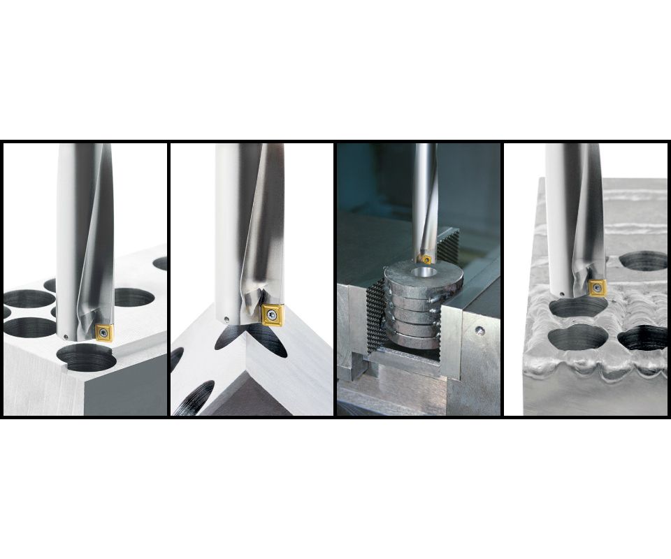
These images show examples of very difficult drilling conditions for an indexable drill. The design of this particular drill provides excellent stability, chip formation, chip evacuation and long service life, making it well-suited for plunge roughing. Images courtesy of Komet of America.
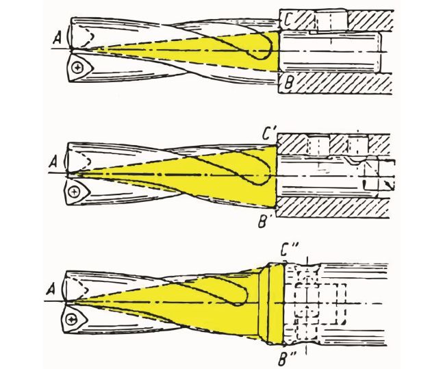
This comparison shows the strength zone of straight-shank (top), flanged (middle) and shank (bottom) tools. While a flanged tool is an improvement over typical straight-shank tools without a flange, it still does not have the same strength zone as a modular drill that has a larger flange diameter and is preloaded to the flange face by the locking screw. This creates some stress in the tool that greatly increases the radial stiffness, making the steel body resistant to bending during plunge roughing or difficult drilling.
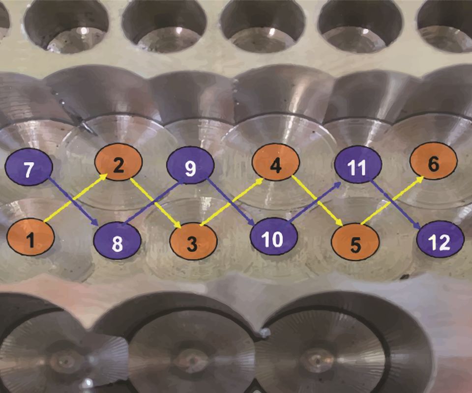
When plunge roughing a chamber or cavity, it is always best practice to drill the solid diameter holes first at a much faster feed rate, then drill the rest of the material between those first holes.
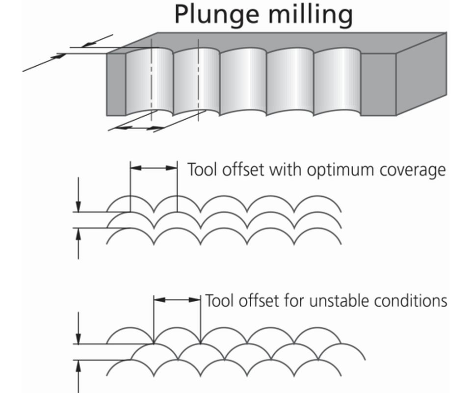
This illustration shows two possible stepover patterns for plunge milling, with the respective maximum stepover width of cut based on the insert land width.


Rough milling operations can take hours on large components and typically remove more than half the raw material by volume. Selecting the proper machining method for the component and machine tool creates a successful and stable system. The use of plunge roughing, commonly referred to as plunge milling, has grown recently as cutting tools that can handle the tough requirements of this machining method have become more readily available.
Plunge roughing uses a cutting tool in an axial direction for material removal, similar to drilling. This process requires a tool that is designed to handle such axial cutting, such as indexable drills and milling tools, two common tool types that each have their own benefits and limitations.


Benefits Breakdown
A drawback of plunge roughing is very limited profile control, since using the tool in a plunging tool path will always leave a radius-shaped scallop on the part equal to the tool radius. So, unlike a traditional milling tool path that can be programmed to create any shape, plunge-milling tool paths cannot create smooth contours. Drilling, by nature, typically offers the highest material-removal rate of all machining operations, so using a drilling operation will create a productive operation with a flexible profile path.
Consider this example to prove the effectiveness of plunge roughing versus high-feed milling: A section of material equivalent to 325 cubic inches needs to be roughed out from a P20-steel block. The two tool choices are a 2-inch-diameter high-feed mill and a 2-inch-diameter indexable drill. The initial cutting parameters of the high-feed mill, when taking a full-width pass, are 825 surface feet per minute (sfm), 0.0315 inch per tooth (ipt), four cutting edges and a depth of cut of 0.078 inch. This equates to 1,570 rotations per minute (rpm) and 198 inches per minute (ipm) with a material removal rate of 30.9 cubic ipm. So the machining time theoretically will be 10.5 minutes, excluding any non-cutting time. The initial drill cutting parameters are 700 sfm with a feed rate of 0.008 inch per revolution (ipr). This equates to 1,337 rpm at 10.7 ipm and yields a material removal rate of 33.6 cubic ipm for a theoretical time of 9.7 minutes.
The mathematics of this example prove that plunge roughing with the indexable drill is favorable in terms of time, however there are many other factors that should also be considered to ensure this is the most economical solution for a particular job, including tool path, material shape, machine power and speed.
Some high-feed mills can achieve a metal removal rate of more than 50 cubic ipm, but very few machines can handle such speeds accurately without problems. Success with high-feed milling is also very dependent upon the tool path as well as minimal non-cutting time in order to reduce cycle time. Plunge roughing, on the other hand, is a much more dedicated solution with fewer variables. Its success is impacted only by speed, feed rate and stepover, whereas a traditional milling operation relies on the same, plus program tool path, dynamic feed rates around radii, tool engagement percentage and toolholder radial stiffness.
Tool Design Elements
Since both indexable drills and most milling tools can be used for these plunge roughing operations, let’s examine the unique aspects of each.
As indexable drill design has improved over time, they have became better candidates for plunge roughing operations. Solid high speed steel (HSS) and carbide drills are typically not good choices for plunge roughing, as their steep point angles can push the tool off center if less than 60 percent of the cutter diameter is engaged in the part material. Also, solid drills do not handle the shock associated with plunging very well. Carbide, for example, can easily break if exposed to high shock loads.
The high-strength steel body of indexable drills, coupled with a complex cutting geometry on the insert, increases the abuse these tools generally can handle. However, not all tools are created equal. Some key design elements for a stable process are drill stability, chip formation and chip evacuation.
For drill stability, the machine, fixturing, tool and toolholding must be considered as one connected system. From a tool standpoint, the goal is to have as stiff of a drill core or web as possible and still be able to smoothly evacuate all chips under all cutting conditions. The core or web of a drill is the area of the tool along the center axis that has no machined flutes. The diameter and longitudinal shape is what creates the radial stiffness of a drill and enables it to resist deflection.
A main difference among drills is coolant channel design. A common way to create a coolant channel is to drill one main feed hole through the center of the tool, then two connecting passages to each insert. This is easy and relatively inexpensive to manufacture, however it does reduce the solid material area in the core. Under light drilling conditions, this may not be an issue, but pushing a tool to its physical limits will be noticeable, especially if it is not fully engaged, which adds a radial load component to the tool itself.
For maximum drilling performance, other drills are designed with two separate, small coolant channels that are drilled through when the tool is in a rough-machined state during manufacture. The tool body is then heated and twisted to match the helix angle of the fluting, creating a completely solid core of the tool and two independent helical coolant channels that take the coolant flow directly to the cutting edge.
From an insert perspective, the cutting edge geometry and position have a huge impact on cutting performance and stability of the drill itself. Since inserts are pressed, they can be given very complex topography that is not possible in grinding solid tools. This, along with a pocket manufacturing method, allows tight control of mounting and position angles, such as the gamma angle that defines the radial angle in relationship to the center line of the drill axis. The angle at which the insert sits, the cutting edge design and the contact point of the insert on the material all determine how forces act on the drill.
Balanced forces around the drilling axis will create a very stable and smooth drilling operation. When the drill is used as a plunging tool, its diameter is not always fully engaged, which makes this process much more difficult as the force vectors change relative to the tool axis. Most high-performance indexable drills are designed with these issues in mind. The better balanced the drill forces are, even under poor conditions, the more aggressive and difficult applications the drill can perform, including, for example, drilling through a step, uneven entry or exit, drilling on a point, or even drilling through a welded seam.
Chip formation is always a critical aspect of a machining operation. The goal is to achieve a consistent chip shape and size, easing chip evacuation. Since complex chipbreaking topographies can be pressed into an insert, it is relatively easy to get a good drill to form a consistent chip when running with the proper insert grade, geometry, coating, speed and feed. Using the tool in a plunging operation adds an interruption to the cut, which aids in chipbreaking, but it also requires an insert edge that can handle the added shock. It is typically advisable to use an insert topography with a large land width and hone for a strong edge, and a suitably strong substrate grade that will not fracture under impact with the material.
Chip evacuation is the final key characteristic of a solid drill that can be used for plunging. Most drills have a flute configuration that is sufficient for solid-diameter drilling, with material completely around the circumference of the tool. However, when plunge milling, the drill will commonly no longer be fully engaged based on diameter, and there will be an open area along the circumference of the tool into which chips will fall instead of falling axially along the drill flutes. Damage will result if the chips that fall through the open area get caught between the tool body and the workpiece. Special care should be taken to ensure the chips are being evacuated cleanly when using a new plunging drill in a difficult application for the first time.
Indexable milling tools can also be used in plunge roughing operations, but they have a more limited stepover equal to their insert land width. This is the length of insert edge that can be used for cutting in that orientation without damage or wear to the second side of the insert that could be used if indexed. If the stepover of the tool is greater than the insert land width, it is possible that the steel body of the tool will also contact the material, causing tool failure and part damage. In turn, the amount of material that can be removed per stroke with indexable milling tools is limited compared to drills of a similar size.
However, there are benefits to using an indexable mill in plunge roughing. For example, it often has a stronger body than a drill, since these tools are much shorter and typically have very small flutes, so radial forces are not as much of an issue. Also, an indexable drill typically only has one effective cutting edge, as the inboard and outboard inserts are not cutting the same path. A mill of similar size will have more effective cutting edges, since all cutting edges are cutting the same path, and this can greatly increase the feed rate per minute, bringing the material removal rate (MRR) closer to that of a drill, even though less material is being removed per pass. In some cases, the MRR may even be greater.
High-feed mills can work very well for plunging applications, as the entry angle of the insert is usually 10 degrees or less. This places most of the forces axially towards the spindle for very high stability. The small entering angle also creates a very wide cutting land, so a relatively large stepover can be used, increasing productivity. Using high-feed mills for plunge roughing also works very well in profile roughing applications, such as along a wall without a lot of material or a very deep or tall part wall, which require a long length-to-diameter ratio for side milling.
Plunging with indexable mills works best when cutting through to an open pocket or along a wall of a part with no floor. Since indexable mills do not cut all the way to center of the tool, it is critical to make sure that the steel body does not contact any material left on the floor of the component by a previous stepover. Sometimes it is necessary to reduce the depth of each stroke when taking multiple steps, so the tool does not contact the floor, which would require material to be removed in another semi-roughing operation.
Whether using a drill or milling tool, the toolholder is just as important. Tool stability is critical to eliminate deflection that can cause tool failure during plunging. Milling tools have a larger body with a large core that is very stable and can be mounted solidly to a spindle adapter. A good rule of thumb is to avoid using a tool that is larger than the diameter of the spindle taper at the spindle nose. This ensures that the forces remain toward the spindle centerline. For example, using a large 6-inch-diameter tool to plunge a component with a CAT40 spindle would create excessive loads too far from the spindle centerline and would most likely deflect, chatter and break inserts.
Since indexable drills have flutes that continue to a certain length up the tool, they are a little weaker by design. This is where the tool connection becomes important. A flange on the tool that will act as a positive stop on the holder is a requirement. However, on traditional straight-shanked tools with a flange, that feature only stops axial movement and does not add any significant radial stiffness. In modular connections, the connection diameter is much larger, and there is a significant increase in radial stiffness even in long projections due to the unique clamping style of the modular connection.
Plunge roughing can be a great alternative to traditional rough machining strategies. It stands out in setups with poor stability in which cutting with axial tool pressure is a much better option. With good operation planning and some time spent optimizing the cutting tools in the system, plunging can be the most productive and stable choice for high-volume material removal.


Related Content

Plastic Prototypes Using Silicone Rubber Molds
How-to, step-by-step instructions that take you from making the master pattern to making the mold and casting the plastic parts.
Read More
The Benefits of Hand Scraping
Accuracy and flatness are two benefits of hand scraping that help improve machine loop stiffness, workpiece surface finish and component geometry.
Read More
Treatment and Disposal of Used Metalworking Fluids
With greater emphasis on fluid longevity and fluid recycling, it is important to remember that water-based metalworking fluids are “consumable” and have a finite life.
Read More
Hands-on Workshop Teaches Mold Maintenance Process
Intensive workshop teaches the process of mold maintenance to help put an end to the firefighting culture of many toolrooms.
Read MoreRead Next

How to Use Continuing Education to Remain Competitive in Moldmaking
Continued training helps moldmakers make tooling decisions and properly use the latest cutting tool to efficiently machine high-quality molds.
Read More
Reasons to Use Fiber Lasers for Mold Cleaning
Fiber lasers offer a simplicity, speed, control and portability, minimizing mold cleaning risks.
Read More
How to Use Strategic Planning Tools, Data to Manage the Human Side of Business
Q&A with Marion Wells, MMT EAB member and founder of Human Asset Management.
Read More