
On-Machine In-Process Inspection Improves Machining Accuracy
High-speed machining with on-machine in-process inspection, machining management, and control technology reduces machining time and eliminates manual bench work.
Share


Selecting the right cutting conditions before machining is critical for precision machining. The wrong conditions can lead to tool deflection and tool wear, which diminishes the dimensional accuracy and surface quality of subsequent workpieces.
Generally speaking, manufacturing engineers and machinists who analyze material hardness, workpiece characteristics and tool selection before machining can obtain a set of suitable cutting parameters. However, most develop the appropriate parameters by test cutting and adjusting because there are no corresponding means to quantify the optimal cutting parameters.


An alternate solution is a high-speed machining center with on-machine in-process inspection, full-scale precision machining management and control technology that uses workpiece inspection to quickly assist machinists with determining suitable cutting parameters that can reduce machining time and eliminate mold fitting time.
Understanding Machining Requirements
An automotive lamp mold is 500 by 900 by 260 mm (19.7 by 35.4 by 10.2 inches) and 600 kg (1,320 lbs) and requires a front and rear mold that each have different dimensional accuracy requirements for different key positions. So, to machine the mold without requiring manual bench work to get the perfect fit, reaching the required dimensional accuracy levels is critical.
Here are key dimensional requirements for the front and rear molds that a machinist must consider to produce a quality product:
Front Mold
The front mold made from NAK80 hardened mold steel determines the lamp’s appearance, so it has a higher surface quality requirement than the rear mold.
· Parting surface. The main function of the parting surface is to seal off the plastic to prevent flash and burrs, so machining accuracy of the parting surface is ±0.01 mm.
· Product (seal-off) surface. Tolerance is within ±0.02 mm, but the surface finish must be better. Otherwise, product appearance will be diminished.
· Kiss-off surface: The front and rear molds are fitted together so the plastic cannot enter and to form the product’s holes. The tolerance requirement is +0.015 mm.
· Fine positioning: The positioning accuracy of these precise positioning modes for front and rear mold fitting (e.g., conical, square, etc.) is 0.01 mm.
· Guide pillar hole and guide pillar: The accuracy required to ensure the correct fitting of the front and rear molds is lower than that of fine positioning. The guide pillar and guide pillar hole must be a clearance fit of 0.01 mm~0.02 mm.
· Positioning corner: The accuracy of a coarse positioning corner is lower than that of fine positioning at 0±0.015 mm.
· Fitting surface: The required tolerance is 0±0.015mm (see Figure 1).
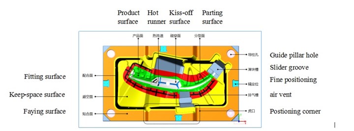
Figure 1. A front lamp mold made from NAK80 hardened mold steel. Figures courtesy of Jingdiao North America Inc.
Rear Mold
The rear mold (Figure 2) is non-surface related, so it has a lower surface quality requirement and is made from LKM 50# hardened steel.
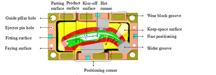
Figure 2. A rear lamp mold made from LKM hardened mold steel.
· Positioning corner. The required tolerance is negative to within -0.03~ -0.01 mm for coarse positioning and easy mold fitting, relative to the front mold.
· Slider groove. The customer positions the slider, which has a required tolerance of -0.02 mm.
· Wear block groove. The wear block is positioned with the fitting surface of the front mold and can be replaced after wear.
· Over-cut fit surface. The tolerance of partial fit positions must be negative and controlled between -0.01 to -0.03 mm.
Achieving Required Machining Accuracy
A high-speed machine tool equipped with on-machine in-process inspection measurement including a probe and laser tool measurement system can quantify the machining process, which allows the machine tool to adjust during the machining process and control the dimensional accuracy of each key position of the final mold.
The front mold’s tolerance as indicated by the on-machine in-process inspection system is as follows: parting surface -0.00827 ~ 0.00575 mm, positioning surface -0.0202 ~ 0.0282 mm, kiss-off surface +0.012 mm and product surface +0.01 mm (Figure 3).
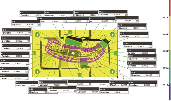
Figure 3: On-machine on-measurement results of a front lamp mold.
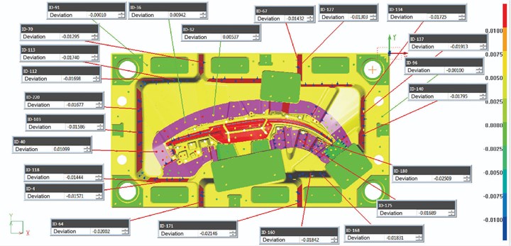
Figure 4: On-machine on-measurement results of a rear lamp mold.
The cutter yielded a glossy surface finish with exceptional consistency, as there was no tool vibration, over-cut at the root part or burr at the edge. The red lead on the parting surface was in good condition after machining at 90% with a uniform distribution. This final fitting result proves the success of standardized moldmaking using machining processes that include on-machine in-process inspection.
Figure 1a shows a precision H13 test mold, on which a machinist used on-machine in-process inspection after finish machining to measure the actual surface allowance. Unsuitable cutting capacity and insufficient rigidity resulted in an allowance deviation range from 0.003 mm to 0.006 mm (compared to the nominal allowance of -0.003~0 mm).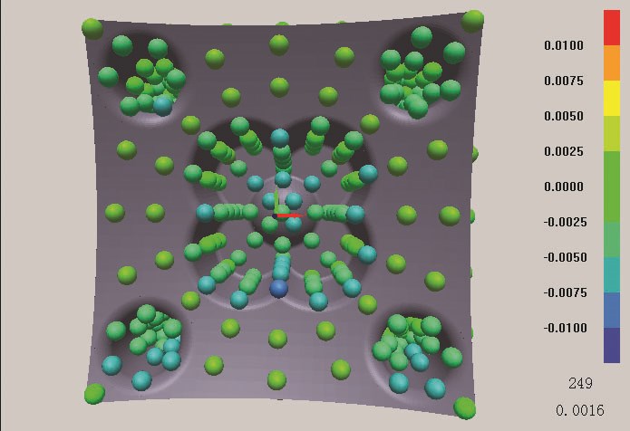
Figure 1b shows that by optimizing the cutting parameters and strictly controlling the tool holder system, the deviation range of the fine positioning surface was reduced to -0.003~0 mm. 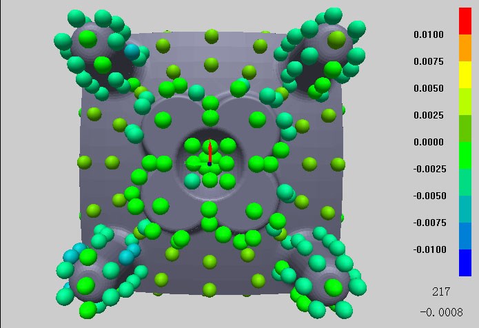


Related Content

The Benefits of Hand Scraping
Accuracy and flatness are two benefits of hand scraping that help improve machine loop stiffness, workpiece surface finish and component geometry.
Read More
Machining Center Spindles: What You Need to Know
Why and how to research spindle technology before purchasing a machining center.
Read More
Plastic Prototypes Using Silicone Rubber Molds
How-to, step-by-step instructions that take you from making the master pattern to making the mold and casting the plastic parts.
Read More
Laser Welding Versus Micro Welding
The latest battle in finely detailed restoration/repair of mold materials.
Read MoreRead Next

How to Use Strategic Planning Tools, Data to Manage the Human Side of Business
Q&A with Marion Wells, MMT EAB member and founder of Human Asset Management.
Read More
How to Use Continuing Education to Remain Competitive in Moldmaking
Continued training helps moldmakers make tooling decisions and properly use the latest cutting tool to efficiently machine high-quality molds.
Read More
Are You a Moldmaker Considering 3D Printing? Consider the 3D Printing Workshop at NPE2024
Presentations will cover 3D printing for mold tooling, material innovation, product development, bridge production and full-scale, high-volume additive manufacturing.
Read More